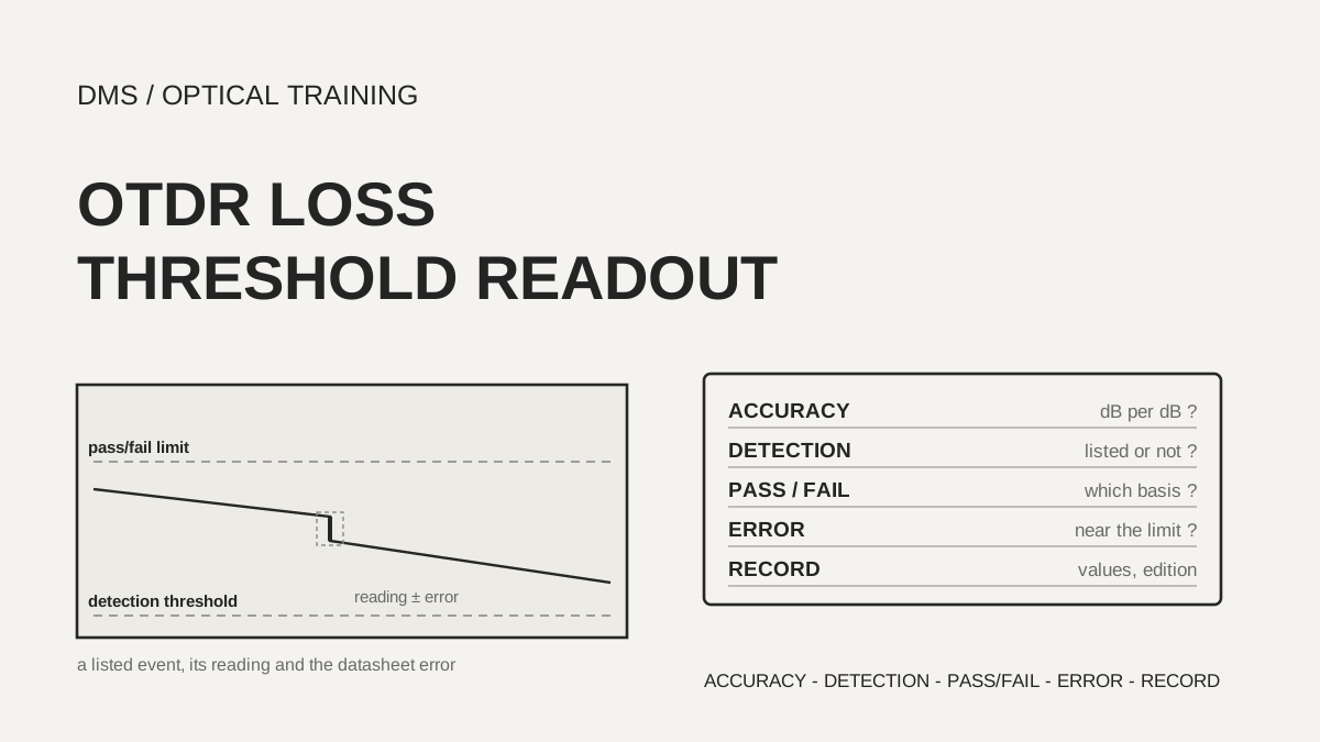
An OTDR (optical time-domain reflectometer) datasheet states loss accuracy as an error per dB of measured loss (dB/dB), the detection threshold on the setup screen is the smallest event the software lists, and the pass/fail threshold is the limit that turns a listed event red. In the ten documents reviewed, the three numbers sit in different places. In a hypothetical case, a splice read as 0.28 dB against a 0.30 dB pass/fail limit lands between 0.18 and 0.38 dB if you apply the largest floor error found, ±0.1 dB, so the verdict can go either way. So copy the measured value into the test record together with the detection threshold, the pass/fail threshold and the name of its standard preset, and the datasheet's error statement.
As of November 7, 2026, based on the manufacturer documents listed under Sources.
Learning objectives
-
Read the loss accuracy (dB/dB) in a datasheet and calculate how large the error is for events of different loss.
-
Separate the detection threshold from the pass/fail threshold on the setup screen and explain which one decides whether an event appears in the table.
-
Read values near a pass/fail limit, and reflectance values, together with the datasheet error, and decide what goes into the test record.
In what unit is OTDR loss accuracy stated?
The datasheets reviewed state loss accuracy as linearity in dB/dB. EXFO's MaxTester 720D and 735D give ±0.03 dB/dB and the 715D gives ±0.05 dB/dB. The VIAVI SmartOTDR 100A/B datasheet gives an attenuation linearity of ±0.04 dB/dB and Fluke's OptiFiber Pro gives ±0.03 dB/dB. Yokogawa's AQ7280 series gives ±0.03 dB/dB for most units and ±0.025 dB/dB for the high-precision AQ7286 units, with a footnote describing narrow test conditions. Anritsu's MT9085 brochure gives ±0.05 dB/dB or ±0.1 dB, whichever is greater, and a Yokogawa footnote states ±0.05 dB when the loss is 1 dB or less.
An Anritsu primer explains why the unit looks like this. An ordinary optical sensor states accuracy as a flat amount such as ±0.10 dB or as a percentage, but an OTDR measures over a very wide range of backscatter levels, so a linearity stated as ± so many dB per dB of measured loss is the better description. The document adds that poor linearity can show up as a trace that rolls off, curves or looks bumpy, that linearity specifications are usually not listed in marketing brochures, and that Fresnel reflections are not considered in a linearity specification. So dB/dB describes the loss read along the backscatter and is not an accuracy figure for reflectance.
As a DMS interpretation, multiplying the dB/dB value by the event loss gives a sense of the error size. The documents do not instruct this multiplication, so it is labeled a DMS calculation. Putting the printed values into hypothetical events of 0.3 dB, 1 dB, 3 dB and 10 dB gives the table below.
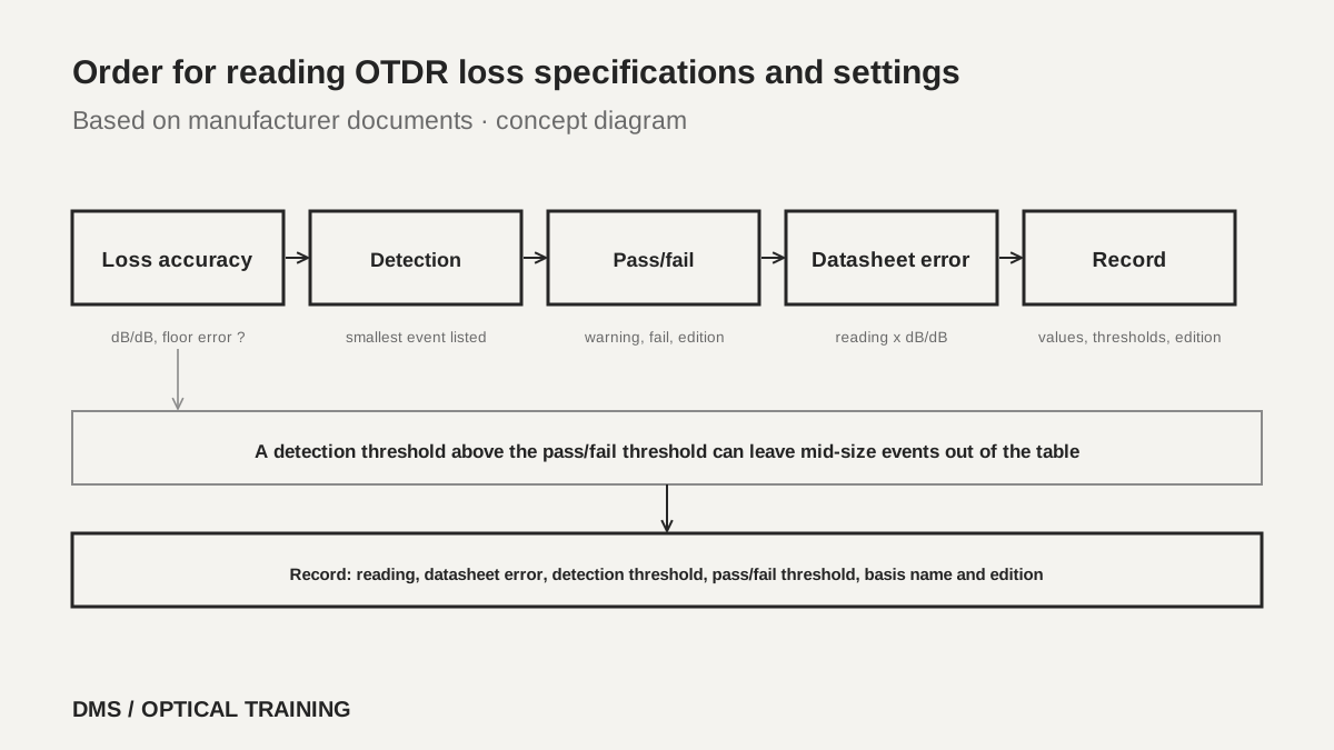 The order for reading loss accuracy, detection threshold and pass/fail thresholdView original
Scroll horizontally to view a wide table.
| Datasheet statement (document) | 0.3 dB event | 1 dB event | 3 dB event | 10 dB event |
|---|---|---|---|---|
| ±0.03 dB/dB (EXFO 720D and 735D, Fluke) | ±0.009 dB | ±0.03 dB | ±0.09 dB | ±0.30 dB |
| ±0.04 dB/dB (VIAVI SmartOTDR 100A/B) | ±0.012 dB | ±0.04 dB | ±0.12 dB | ±0.40 dB |
| ±0.05 dB/dB (EXFO 715D) | ±0.015 dB | ±0.05 dB | ±0.15 dB | ±0.50 dB |
| ±0.05 dB/dB or ±0.1 dB, whichever is greater (Anritsu MT9085) | ±0.10 dB | ±0.10 dB | ±0.15 dB | ±0.50 dB |
| ±0.05 dB up to 1 dB, ±0.03 dB/dB above (Yokogawa AQ7280, most units, footnote 14) | ±0.05 dB | ±0.05 dB | ±0.09 dB | ±0.30 dB |
The values in the table are DMS calculations that put printed formulas into hypothetical losses, and they are not a performance test of any instrument. The notable point is that the order flips for small losses. At a 0.3 dB event the EXFO 720D calculation is ±0.009 dB while the Anritsu floor is ±0.1 dB, more than ten times larger, but at 10 dB the figures come together at ±0.30 dB and ±0.50 dB. The EXFO, VIAVI and Fluke pages read here contained no floor-error wording. Missing wording does not mean there is no floor, so it stays on the list of things to confirm.
Scroll horizontally to view a wide table.
| Document and edition | Loss-related datasheet lines | Conditions and notes |
|---|---|---|
| EXFO MaxTester 720D (MAX720D.7EN, marked 2025-08) | Linearity ±0.03 dB/dB, Loss threshold 0.01 dB, Loss resolution 0.001 dB | No condition footnote letter beside the linearity value |
| EXFO MaxTester 715D (MAX715D.6EN, marked 2025-08) | Linearity ±0.05 dB/dB, Loss threshold 0.01 dB, Loss resolution 0.001 dB | Same table layout |
| EXFO MaxTester 735D (MAX735D.3EN, marked 2026) | Linearity ±0.03 dB/dB, Loss threshold 0.01 dB, Loss resolution 0.001 dB | Same table layout |
| VIAVI SmartOTDR 100A/B (30176148 907 1222) | Attenuation linearity ±0.04 dB/dB, attenuation resolution 0.001 dB | No threshold line on the pages read |
| Fluke OptiFiber Pro (no revision mark) | Linearity ±0.03 dB/dB, reflectance uncertainty ±2 dB | HDR module specification page |
| Yokogawa AQ7280 (BUAQ7280-01EN) | Loss accuracy ±0.03 dB/dB, AQ7286 ±0.025 dB/dB, return loss accuracy ±2 dB | Footnote 14: ±0.05 dB for loss of 1 dB or less; footnote 15: narrow test conditions |
-
Check first whether loss accuracy is stated in dB/dB or in dB
-
Read down to the footnotes for a floor error such as ±0.05 dB up to 1 dB
-
For small losses a floor error can reorder datasheets that show the same linearity number
Are the datasheet's loss resolution and loss threshold the same as accuracy?
They are not. The EXFO table prints Loss threshold 0.01 dB and Loss resolution 0.001 dB on separate lines right beside the linearity line, and the VIAVI datasheet likewise separates an attenuation resolution of 0.001 dB from the ±0.04 dB/dB linearity. Resolution says how many digits the display shows, so a loss shown to the third decimal place does not mean the error is 0.001 dB. This reading is a DMS interpretation and not something the datasheets spell out.
EXFO's Loss threshold of 0.01 dB is a single line, and from the page read it was not possible to tell whether it is the smallest loss the instrument detects as an event, the lowest value of a pass/fail setting, or the smallest unit of displayed loss. So this value is not treated as the same thing as a threshold on the setup screen and stays on the list of things to confirm.
What is the difference between a detection threshold and a pass/fail threshold?
A detection threshold decides whether the software puts an event in the table, and a pass/fail threshold decides whether a listed event is marked failed or as a warning. The VIAVI 4100 series user manual (Rev. 011) puts the two in different menus. Under Advanced, the Detection Thresholds let you enter a minimum splice level from 0.01 dB to 1.99 dB or choose No or Auto, and for reflectance a level from −98 dB to −11 dB, None, or All. Fiber end is Auto (recommended) or a manual value from 3 dB to 20 dB in 1 dB steps, and bend is detected automatically above 0.30 dB. Pass/fail is set separately in the Alarms menu, whose levels are None, Warning and Fail.
The Yokogawa AQ7280 user manual (IM AQ7280-01EN, 10th edition, August 2022) also separates the two settings. Under the event search conditions, a connector or splice loss that exceeds the threshold is detected as an event (0.01 dB to 9.99 dB), a reflection is detected when the return loss is at or below the threshold (20 dB to 70 dB), and the end of fiber is 3 dB to 65 dB. Pass/fail judgment is a separate menu: it is performed on the events detected in the waveform, and events that exceed the threshold are shown as fault events with an asterisk. The manual also states that the end of a fiber is handled as either a splice loss or a reflection, so there is no fault event just for the end of a fiber.
An Anritsu primer shows the effect on the detection side. If the analysis sensitivity threshold is set to 0.20 dB, the software will not mark splices with lower loss, and at the far end of a very long fiber the noise can make the software find an event that is not there, which longer averaging reduces. The Fluke OptiFiber Pro data sheet describes event editing: a splice hidden by noise or smaller than the minimum detection threshold can be inserted as a 0 dB event, the link pass/fail status is then updated, and edited events are marked in reports. The same document says an APC connector can be identified as a splice because both are non-reflective, which matters because the loss budget of a splice is smaller than that of an APC connector, and editing lets you correct it. The Anritsu MT9085 brochure says events at PON splitters are evaluated pass/fail against preset threshold values.
As a DMS interpretation, if the detection threshold is set higher than the pass/fail threshold, events of a size in between may never appear in the table and so never get judged. The Yokogawa manual says judgment is performed on detected events, which supports this directly. The VIAVI manual contains no matching statement on the pages read, so the same structure is not assumed there and it stays on the list of things to confirm.
Scroll horizontally to view a wide table.
| Document | Detection settings (what gets listed) | Pass/fail settings (warning and fail) |
|---|---|---|
| VIAVI 4100 manual (Rev. 011) | Splice 0.01–1.99 dB or No/Auto, reflectance −98 to −11 dB or None/All, fiber end Auto or 3–20 dB, bend Auto (above 0.30 dB) | Alarm level none, warning or fail, user values or a standard preset |
| Yokogawa AQ7280 manual (10th ed.) | Connector and splice loss 0.01–9.99 dB, return loss 20–70 dB, fiber end 3–65 dB | Connector loss, splice loss, return loss, splitter loss, dB/km and total loss, applied to detected events |
| Anritsu primer | With the threshold at 0.20 dB, splices of lower loss are not marked | Not found on the pages read |
| Anritsu MT9085 brochure | Splitter branches and threshold values can be preset in Fiber Visualizer | PON splitter events evaluated pass/fail against preset thresholds |
| Fluke OptiFiber Pro | Splices below the minimum detection threshold may be missing, and can be inserted as 0 dB events | Link pass/fail updates after an edit, and edited events are marked in reports |
-
The detection threshold sets whether an event reaches the table, and the pass/fail threshold sets what color and verdict it gets
-
Check on the setup screen that a detection threshold is not set higher than a pass/fail threshold
-
Check that manually inserted or edited events are marked as edited in the report
How are pass/fail thresholds tied to standard names?
In the VIAVI manual the pass/fail setting is either values you enter or a preset that carries a standard's name. For single-mode modules the Default sets failure above 0.30 dB for a splice, above 0.50 dB for a connector, above −35 dB for reflectance, above 1.00 dB/km for slope and below 27 dB for link ORL, with no multiplexer/demultiplexer item (No). The standard-named presets are in the table below, and splice loss is above 0.30 dB in every one. These figures are the values the manual puts in each preset and not clauses read from the standards themselves.
Scroll horizontally to view a wide table.
| Preset name (single mode) | Connector loss | Reflectance | Slope |
|---|---|---|---|
| TIA-568.3 | above 0.75 dB | not judged | above 1.00 dB/km |
| TIA-568.3 RL35 | above 0.75 dB | above −35 dB | above 1.00 dB/km |
| ISO/IEC 11801 (2010) | above 0.50 dB | above −35 dB | above 0.40 dB/km |
| ISO/IEC 14763-3 (2014) | above 0.75 dB | not judged | above 0.40 dB/km |
| ISO/IEC 14763-3 (2019) | above 0.75 dB | above −35 dB | above 0.40 dB/km |
| IEC 61280-4-5 (2020) | above 0.75 dB | above −35 dB | above 0.40 dB/km |
Standards from the same family differ by edition. The ISO/IEC 14763-3 preset of 2014 does not judge reflectance while the 2019 preset judges above −35 dB, and for multimode the ISO/IEC 11801 (2010) preset sets connector loss above 0.30 dB and reflectance above −20 dB. A test report therefore needs the edition year as well as the standard name. The warning level shows results between the warning threshold the user chose and the fail threshold in yellow, and the manual says results that are very close to a fail value without exceeding it are also shown in yellow.
-
Write the edition year together with the name of the pass/fail basis
-
Keep the numbers in a preset apart from the clauses of the standard itself
-
Check whether the preset in use has reflectance judgment switched off (not judged)
What if datasheet error overlaps a pass/fail threshold?
The situations below are hypothetical teaching cases and not a real site or measurement. First, a splice is displayed as 0.28 dB and the pass/fail limit is above 0.30 dB. The displayed value passes, but as a DMS calculation the Anritsu floor of ±0.1 dB puts the real value between 0.18 and 0.38 dB, and the 0.30 dB limit sits inside that range. Calculating with the EXFO 720D's ±0.03 dB/dB narrows it to 0.271–0.289 dB, which stays under the limit, but that is a result of the multiplication reading and not something the datasheet guarantees. As a DMS interpretation, a value within the datasheet error of the limit is not confirmed as a pass. Measure again in the opposite direction on the same wavelength or check it against another method, and record the basis.
Second, the detection threshold is higher than the pass/fail threshold. Suppose a VIAVI setup has the splice detection threshold at 0.50 dB and a fail limit of above 0.30 dB. A 0.40 dB splice falls short of the detection threshold and may not appear in the table. VIAVI lets you enter a detection value up to 1.99 dB, and the pages read do not show whether the setup screen blocks such a combination. In that case the absence of a fail mark does not mean there is no problem, so the detection threshold has to be written in the record as well.
Third, reflectance. If the limit is above −35 dB and the display shows −34 dB, the value is above the limit and fails, but EXFO, Fluke and Yokogawa state reflectance accuracy as ±2 dB, so the real value may lie between −36 and −32 dB. Anritsu states ±2 dB for single mode and ±4 dB for multimode, and gives the single-mode condition as measuring the non-connected end of a fiber of about 25 km with a distance range of 50 km and a 2 μs pulse width. Sign conventions also differ between instruments: VIAVI writes thresholds as negative reflectance such as −35 dB while Yokogawa writes a positive return loss from 20 dB to 70 dB. As a DMS interpretation, a reflectance of −35 dB is the same size as a return loss of 35 dB. Reading the sign or the direction the wrong way turns a pass into a fail.
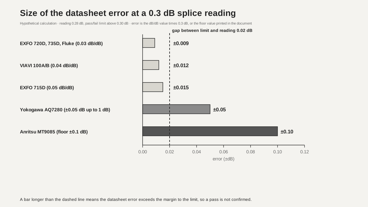 Size of the datasheet error at a 0.3 dB splice readingView original
-
If the gap between a reading and the limit is smaller than the datasheet error, do not fix the verdict
-
Check the detection threshold and the pass/fail threshold on the same screen
-
Copy reflectance with the instrument's sign and inequality direction (above, at or below)
What goes into the test record?
The record should carry the OTDR model and module, pulse width, averaging time, wavelength, the detection thresholds (splice, reflectance, fiber end), the pass/fail thresholds, the name and edition year of the pass/fail basis, whether the warning level was used, the position of and reason for any manually edited event, and the datasheet's loss accuracy statement (whether it is dB/dB and whether a floor error exists). A value close to a limit should not be recorded only as pass or fail, but with the reading and the datasheet error side by side.
The documents reviewed carry these dates. EXFO's 720D and 715D are marked August 2025 and the 735D is marked 2026, and the Anritsu brochure is marked printed July 30, 2024. The VIAVI user manual is marked November 25, 2025, and the SmartOTDR datasheet is a distributor copy with a search-listing date of December 19, 2022. No revision mark was found inside the Fluke data sheet. The Yokogawa datasheet has a search-listing date of May 15, 2026 and its user manual is the 10th edition of August 2022. The Anritsu OTDR primer shows no date and uses an older format that mentions floppy disks, so it was used only for concepts.
This lesson is limited to ten manufacturer documents. A standard text defining loss linearity, whether the datasheet values are typical or guaranteed, the exact meaning of EXFO's Loss threshold of 0.01 dB, the relation between detection and pass/fail judgment in VIAVI, and the standard clauses behind the pass/fail presets were not read or not found. Current-model values, real instrument loss test results and delivery acceptance criteria were not confirmed either.
-
Write the detection threshold, pass/fail threshold, basis name and edition together in the record
-
For a value near a limit, write the reading and the datasheet error together
-
Do not leave unconfirmed items blank; write that they were not confirmed
Checklist
-
Did you find whether the loss accuracy in your OTDR datasheet is stated in dB/dB and whether a separate floor error exists?
-
Did you confirm on the setup screen that the splice and reflectance detection thresholds are not higher than the pass/fail thresholds?
-
Did you copy the name and edition year of the pass/fail basis to the top of the test record?
-
Did you write the datasheet error next to a value close to a limit and decide whether to retest?
-
Did you check the sign of the reflectance notation (negative reflectance or positive return loss) and the inequality direction?
Review questions
1. About how large is the error when an OTDR whose datasheet states ±0.03 dB/dB measures a 3 dB event?
Answer and explanation: 0.03 dB/dB × 3 dB gives ±0.09 dB. The multiplication is a DMS interpretation, not a method the document instructs.
2. How do you read a splice shown as 0.28 dB against a 0.30 dB pass/fail limit with the Anritsu statement (±0.05 dB/dB or ±0.1 dB, whichever is greater)?
Answer and explanation: 0.05 × 0.28 is 0.014 dB, so the greater value of ±0.1 dB applies and the real value is between 0.18 and 0.38 dB. The 0.30 dB limit is inside that range, so do not confirm a pass; record a retest or a check by another method.
3. What happens to a 0.40 dB splice if the splice detection threshold is 0.50 dB and the fail limit is above 0.30 dB?
Answer and explanation: It falls short of the detection threshold and may not appear in the event table. The Yokogawa manual says pass/fail judgment is performed on detected events. An event that is not in the table is not marked failed, so keep the detection threshold below the pass/fail limit and write it in the record.
Sources
-
EXFO: MaxTester 720D specification sheet · MAX720D.7EN, marked 2025-08, PDF page 8 linearity, Loss threshold and Loss resolution
-
EXFO: MaxTester 715D specification sheet · MAX715D.6EN, marked 2025-08, PDF page 8
-
EXFO: MaxTester 735D specification sheet · MAX735D.3EN, marked 2026, PDF page 9
-
Anritsu: ACCESS Master MT9085 series brochure · MT9085series-E-A-1-(5.00), marked printed 2024-07-30, PDF pages 4, 8 and 14
-
Anritsu: Understanding OTDRs · no date shown, PDF page 18 loss linearity and page 37 analysis thresholds
-
VIAVI: SmartOTDR 100A/B series data sheet · 30176148 907 1222, distributor copy, search-listing date 2022-12-19, page 3
-
VIAVI: OTDR 4100 series modules user manual · 700MAN201 Rev. 011, marked 2025-11-25, printed pages 43–44 and 50–52 (PDF pages 59–60 and 66–68)
-
Fluke Networks: OptiFiber Pro data sheet · search-listing date 2021-07-08, no revision mark inside, PDF pages 16 and 28
-
Yokogawa: AQ7280 series OTDR datasheet · BUAQ7280-01EN, search-listing date 2026-05-15, PDF pages 16–17 specifications and footnotes 14 and 15
-
Yokogawa: AQ7280 OTDR user's manual · IM AQ7280-01EN 10th edition, August 2022, printed pages 2-3, 2-11 and 2-13 to 2-15 (PDF pages 31, 39 and 41–43)