An OTDR loss difference at two wavelengths is evidence for a suspected bend, not proof of a bend or a passing link. First match the same fiber, direction and physical event, then check whether loss is greater at the longer wavelength. Record the instrument detection setting separately from the contractual acceptance limit.
Based on manufacturer publications checked on 17 October 2026. Document editions and limits of applicability are identified below.
Learning objectives
-
Pair event losses at the same physical location.
-
Distinguish wavelength difference from detection and acceptance limits.
-
Document valid retests and reasons to withhold a verdict.
Which loss should be compared?
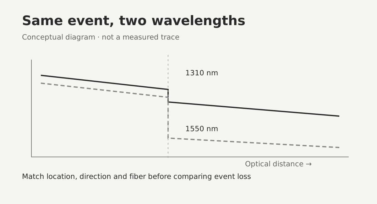 Conceptual pairing of one event at two wavelengthsView original
This lesson concerns stored OTDR results from an inactive singlemode link approved for testing. Low total link attenuation and a locally bend-sensitive event can coexist. Fiber-section attenuation over distance is not the same quantity as loss at one event. Mixing them into a single result prevents a useful location-based diagnosis. It can also conceal a local issue behind a favorable overall loss figure.
EXFO Application Note 194, copyright 2017, and the VIAVI white paper carrying a 2021 copyright describe the tendency for macrobend loss to increase at longer wavelengths. Here the comparison pairs event losses at 1310 and 1550 nm. It does not subtract the vertical heights of two displayed traces or the total accumulated losses of a whole link. Each event value must come from usable backscatter sections around the event.
A non-reflective step is not sufficient to identify a bad fusion splice: splices and bends can both appear as non-reflective losses. Equally, a small wavelength difference does not certify the mechanical routing. Fiber design, the actual bend and measurement sensitivity affect what becomes visible. Keep optical screening separate from checking the cable and tray manufacturer’s installation conditions.
-
Scope: approved, inactive singlemode link
-
Compare: loss at the same event, in dB
-
Do not subtract total link losses or trace heights
Matching the same physical event
Check cable ID, fiber ID, test direction and wavelength before comparing files. Matching event numbers alone is insufficient. If the analysis misses a small event at one wavelength, later event numbers can shift. Compare optical distance, the sequence of neighboring connections and the stored raw traces. An opposite-direction result uses a different distance origin and cannot simply be overlaid as though the starting point were unchanged.
Displayed distance depends on the refractive-index setting and the start reference. Record wavelength-specific fiber settings and launch/receive arrangements, then establish that the same section is being matched. This lesson does not prescribe one universal index number for every wavelength or fiber. Use the settings appropriate to the actual fiber and instrument manual, and keep the evidence supporting the event match.
Different pulse widths or averaging times require a separate comparability check. Rather than forcing every wavelength to use an identical number, verify that the event can be resolved and that sufficient signal remains. A merged pair of events or a step hidden in recovery after a reflection is not a sound input for subtraction. Obtain valid event measurements before calculating a wavelength difference.
-
Match IDs, direction and surrounding events
-
Record index, distance reference and test cords
-
Require resolved events and adequate signal
Loss difference versus detection setting
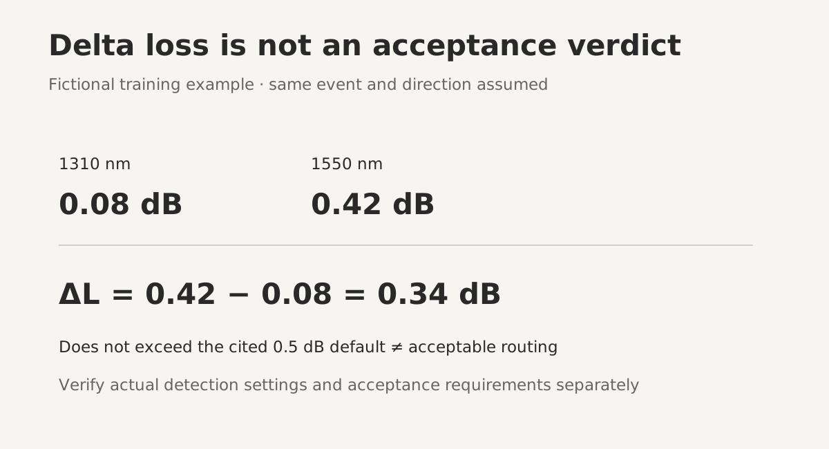 Fictional delta-loss calculation and detection distinctionView original
For this lesson, delta loss is the longer-wavelength event loss minus the shorter-wavelength event loss. A positive result means that the recorded loss is larger at the longer wavelength. Its sign alone does not establish the cause. Check the actual detector’s difference threshold and analysis conditions. Do not take an absolute value to manufacture a bend flag when the order is reversed, and do not substitute a value for missing data.
Printed page 40 of the EXFO OTDR User Guide, version 7.0.1.1, describes detection when the larger loss occurs at the longer wavelength AND the difference exceeds the configured delta. The documented default is 0.5 dB and can be changed. That edition limits this feature to singlemode wavelengths and states restrictions for filtered wavelengths and single-wavelength ports. These are documented conditions for that edition, not a promise about every current instrument.
Page 3 of the VIAVI white paper uses a difference greater than 0.2 dB in its bend explanation. Do not merge this explanatory number with the EXFO software default, or treat either as a stricter contractual acceptance rule. They have different documentary purposes. Record the model, software edition, wavelength pair, actual detection setting and source of the acceptance limit separately so that another reader can interpret the report.
-
ΔL = L1550 − L1310
-
EXFO older-guide default: 0.5 dB, adjustable
-
VIAVI explanatory value: >0.2 dB, not a universal pass limit
Non-detection and inconclusive results
A no-macrobend message still requires checking that detection was enabled and both required wavelengths were acquired. Printed page 101 of the EXFO guide explains that a summary may be incomplete before analysis is finished, and that inappropriate parameters produce another status. Retain non-detection as a result under the stated settings, not proof that no physical bend exists anywhere in the routing.
Event loss is unreliable if the far-end signal has merged into noise or the detector has not recovered sufficiently after a strong reflection. An empty loss field at one wavelength is not 0 dB. Improve the acquisition using settings appropriate to the actual instrument, including the trade-off between short pulses for local resolution and adequate signal at the far end. A displayed number alone does not establish a valid comparison.
Bidirectional measurements can help examine apparent splice loss caused by backscatter differences between dissimilar fibers. However, subtracting 1310 nm from one direction and 1550 nm from the other mixes direction and wavelength effects. Match events within each direction and, where needed, perform wavelength-specific bidirectional analysis before interpreting the difference. This lesson does not guarantee that every splice has wavelength-independent true loss.
-
Missing event loss is not zero
-
No detected bend is not proof of no bend
-
Separate directional effects from wavelength effects
A fictional record and a controlled retest
Assume a fictional training record gives 0.08 dB at 1310 nm and 0.42 dB at 1550 nm for the same event. The difference is 0.34 dB. It does not exceed the 0.5 dB default described in the cited EXFO edition. That does not establish acceptable routing, nor does the explanatory VIAVI number become a contractual rejection limit. These values illustrate interpretation only; they are not field measurements.
The DMS training interpretation is to mark a suspected bend location and hand over the raw traces with the settings. If physical inspection has been approved, check tray routing, cover pressure and stored slack at that location against the applicable manufacturer instructions. Do not intentionally tighten a fiber bend to test the hypothesis, and do not lift an operating tray without the required operational permission.
After an authorized routing correction, reacquire both wavelengths on the same fiber and direction while retaining the earlier files. A reduction is evidence that the intervention may have helped, not proof of contractual acceptance or long-term reliability. If settings changed, first assess whether the before/after difference is comparable. Keep the job open until the required mechanical conditions and optical results have both been checked.
-
0.42 − 0.08 = 0.34 dB
-
No flag and acceptable routing are different claims
-
Retain before/after traces and settings
Handover and remaining verification
A useful handover identifies the cable, fiber, direction, wavelength pair, event location, individual losses and calculated delta. Include the instrument model, software, actual detection setting and trace filenames. These fields let another engineer reproduce the reasoning. If the cause is unresolved, use suspected bend or comparison unavailable rather than a definite fault label that goes beyond the evidence.
The verified material here is the comparison principle and the detection descriptions in the cited manufacturer publications. Current standard clauses, project acceptance requirements, current instrument screens and real-device performance were not verified. This is not permission to apply an ordinary dual-wavelength test to live traffic. In-service testing requires separately verified service wavelengths, filtering, ports and an approved safety procedure.
Related lessons on enclosure routing and far-end measurement conditions help turn a suspect location into a concrete inspection task. For the actual work, the current cable and tray model instructions and the project test procedure take priority over broad numbers in introductory lessons. If a verdict lacks evidence, record the missing condition and the next responsible check instead of adjusting a value to obtain a pass.
-
IDs, direction, wavelengths, event and delta
-
Model, edition, actual detector setting and raw files
-
Withhold acceptance when its requirements are unknown
Handover checklist
-
Are fiber, direction and physical event matched?
-
Are raw traces and wavelength-specific settings retained?
-
Are noise, recovery and neighboring events checked?
-
Are detection and acceptance limits recorded separately?
-
Is non-detection kept separate from absence of bends or acceptance?
Review questions and answers
1. What is the delta for 0.08 dB and 0.42 dB?
If 0.42 dB is the longer-wavelength loss, ΔL is 0.34 dB. This is a fictional example, not a common acceptance limit.
2. Does no flag at the older EXFO 0.5 dB default mean the routing passes?
No. It describes the configured detection result. Valid measurements and separate contractual and manufacturer requirements are still needed.
3. What should replace a missing 1550 nm event loss?
No numerical substitute. Mark the comparison unavailable, improve signal, recovery, resolution, acquisition or settings as appropriate, and retest.
Sources and scope
-
EXFO OTDR User Guide, version 7.0.1.1, ©2013–2015: printed pp.40, 42, 101 (PDF48, 50, 109): wavelength pairs, delta, feature limitations and summary state. Not verification of a current interface.
-
VIAVI, Macrobend Detection Using an OTDR, ©2021, macdet-wp-fop-tm-ae: pp.2–3: wavelength sensitivity and the >0.2 dB explanation, not a universal acceptance requirement.
-
EXFO, Fundamentals of an OTDR, Application Note 194, ©2017: pp.1–2: non-reflective events, dual-wavelength comparison and dead zones.
-
Fluke Networks, OTDR Guide: web edition and publication date unspecified; Troubleshooting with an OTDR and Test Parameters.
Technical facts are independently summarized with DMS training interpretation. No source photographs, charts or interface screenshots are reproduced. Real-device tests, current standard clauses and project acceptance limits remain unverified.