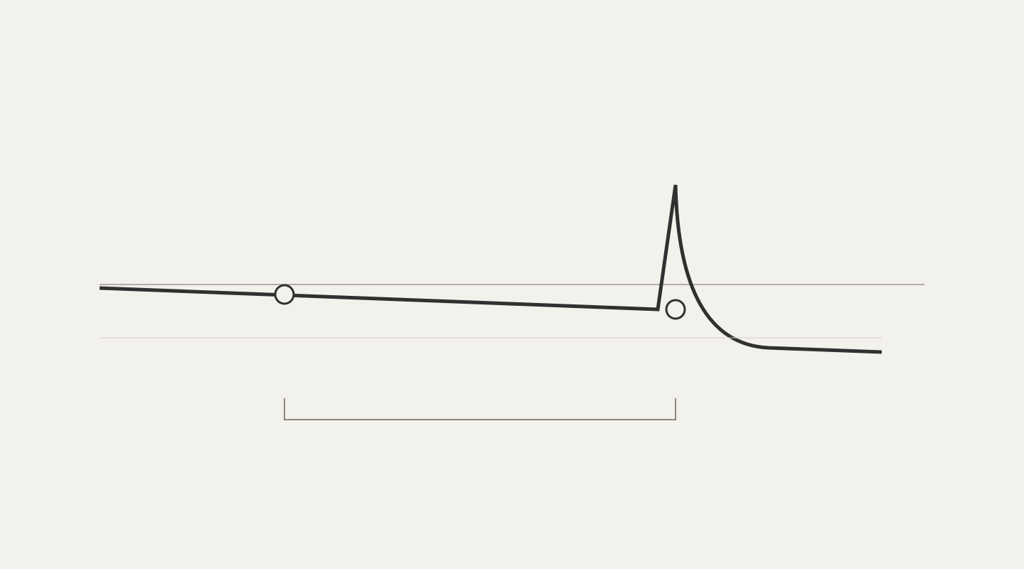
To assess the loss of a far-end connector with an OTDR, attach a receive fiber beyond the link and confirm that the backscatter after the connection has recovered enough to support loss analysis. A visible reflection peak alone does not establish a connector-loss measurement. Select the test leads for the actual instrument and pulse settings rather than treating one fixed length as suitable for every link.
The EXFO Application Note 298, the VIAVI data sheet and the Fluke Networks official explanations were checked on 14 October 2026. The EXFO note is a 2014 document; the VIAVI sheet carries document code 30193711 901 0425 and a 2025 copyright date. The recording sequence below is a DMS teaching recommendation. This lesson does not verify clauses or acceptance limits in a current standard. Use the manual for the instrument in service and the agreed project specification first.
Learning objectives
- Separate a far-end reflection from a measurable mated-connector loss.
- Explain launch and receive fibers and the boundaries used for reporting.
- Identify records that support assessment and records that need a retest.
1. An end reflection and a loss value
On screen: Seeing a peak is not the same as measuring connector loss.
Instructor notes: An optical time-domain reflectometer records returned backscatter and reflected light against distance. A peak near the end provides information about a reflective event. Connector loss is estimated by comparing backscatter levels on either side of the event. With no fiber beyond the event, or with only an unrecovered signal after it, the trace may not provide a usable comparison interval. Reflectance and connection loss are related observations, but they are not interchangeable values.
Consider a test link that ends at a patch panel with nothing attached. Seeing the end location alone does not qualify the loss of the mated connector pair at that termination. Reporting an open-end reflection as the loss of a working connection changes the object being tested. Identify the intended port and connection boundary on the drawing first, then attach the receive lead at that boundary for the assessment.
The existing OTDR fundamentals lesson covers traces and fault location. The event-table lesson addresses automated analysis errors. Both linked curriculum lessons have English bodies. This supplementary lesson concentrates on the conditions needed to measure a far-end connection and record its test boundary.
2. Launch and receive fibers
On screen: Launch fiber provides the before interval; receive fiber provides the after interval.
Instructor notes: Place the launch fiber between the instrument and the link. It provides distance for recovery after the instrument-side reflection and an interval of fiber before the first link connection. Attach the receive fiber at the opposite end. It adds fiber beyond the last link connection so that its loss and reflectance can be assessed. Both leads sit outside the link under test, but both appear in the acquired trace.
VIAVI explains that test-lead fiber characteristics should match those of the link, including type, core size and mode field diameter. EXFO also discusses matching fiber type and geometrical characteristics. A lead is not suitable simply because its plugs fit. Check the fiber and termination specifications, and distinguish defects or contamination in the test lead from a problem in the link termination. The measurement is of the connected arrangement, not an isolated connector in a box.
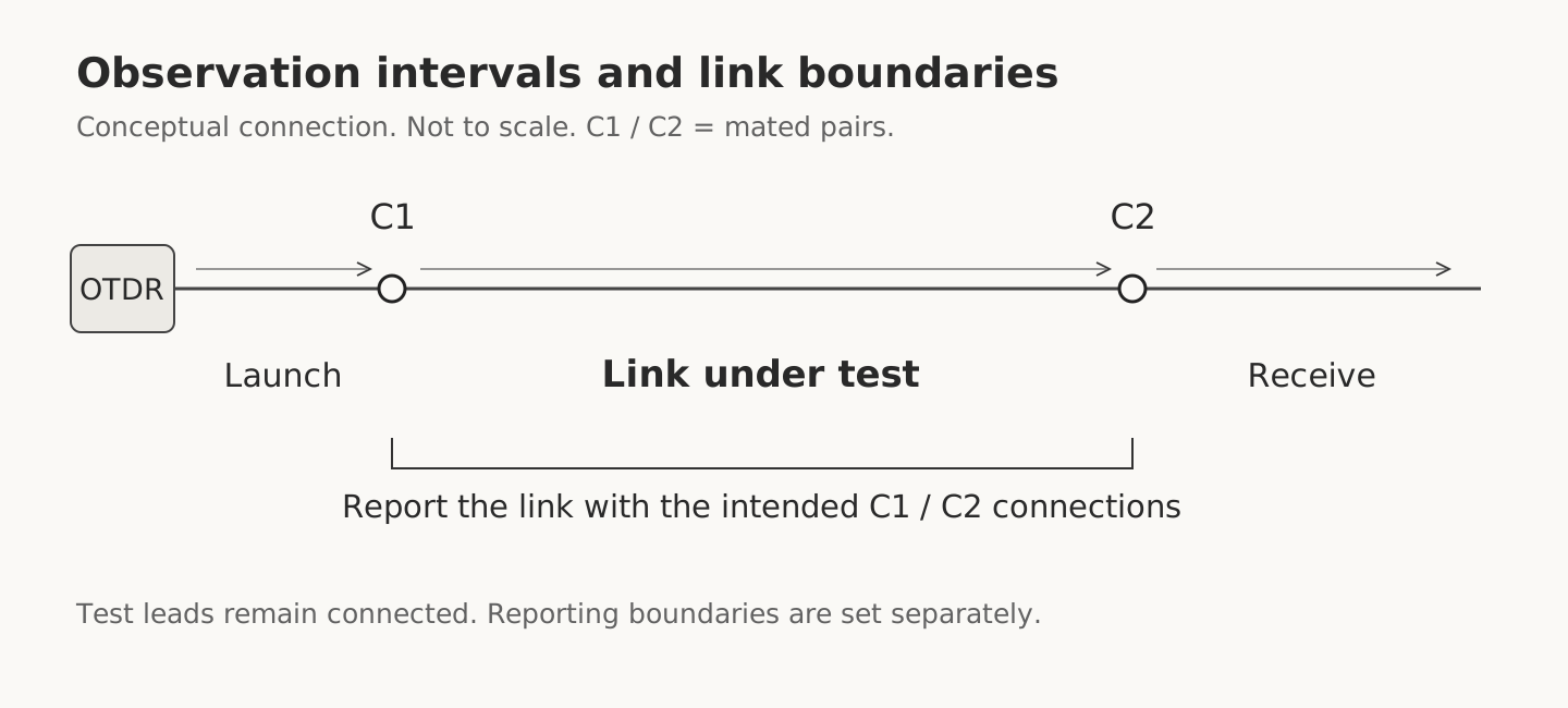 OTDR, launch fiber, link under test and receive fiber, with connection and reporting boundariesView original
Original DMS schematic, not drawn to scale or to a product design. C1 and C2 are the mated connection pairs at the two link ends.
3. How long should the receive fiber be?
On screen: Verify recovery on the actual trace, not just the lead label.
Instructor notes: Select length for the instrument, intended pulse width, fiber type and reflective connections. EXFO's 2014 discussion identifies fiber type, the maximum test length that determines the largest pulse width, and connector type as launch-lead selection factors. Its length calculation concerns launch leads, not a dedicated receive-lead sizing formula. VIAVI calls for a launch lead long enough to measure the first connection and a receive lead of similar length for measuring the last connection. Neither explanation makes a single catalog length a universal guarantee of suitability.
Fluke Networks distinguishes the event dead zone from the attenuation dead zone needed for an event-loss measurement. The checks below are a DMS teaching interpretation linking that principle with the manufacturers’ lead explanations. Two reflection peaks may be distinguishable even when the signal between them is unsuitable for a dependable loss calculation. Recovery conditions can change with pulse width. A lead that supported one acquisition is not automatically suitable after switching to a longer pulse. Inspect the recovered interval after the far-end connection and its separation from the receive fiber's own end event.
If the region beyond the far-end connection remains close to noise or overlaps the receive-end event, withhold assessment under those conditions. Consider an appropriate shorter pulse or a more suitable lead, while also checking whether the shorter pulse still gives adequate signal at the link end. Instruments differ in automatic setup and analysis features. Do not turn the indication on one model's screen into a universal statement about OTDR operation.
4. Acquisition and reporting boundaries
On screen: Connect the receive fiber, then identify the actual link end.
Instructor notes: Adding launch and receive leads makes the full acquired trace longer than the link under test. If a test lead's end is mistakenly selected as a link boundary, its length and loss can enter the reported link result. EXFO illustrates offset or zeroing with launch and receive leads to present both ODF connections. Check the instrument manual for the actual names, settings and behavior of the corresponding compensation functions.
Compensation does not physically remove a test lead. The lead remains connected to provide the observation interval; the reporting settings define the link boundaries within that arrangement. When both end connections are to be assessed, confirm that those mated pairs remain in the intended reported scope. DMS recommends recording the start and end events, lead identifiers, applied lengths and included connections, rather than preserving only a note that compensation was enabled.
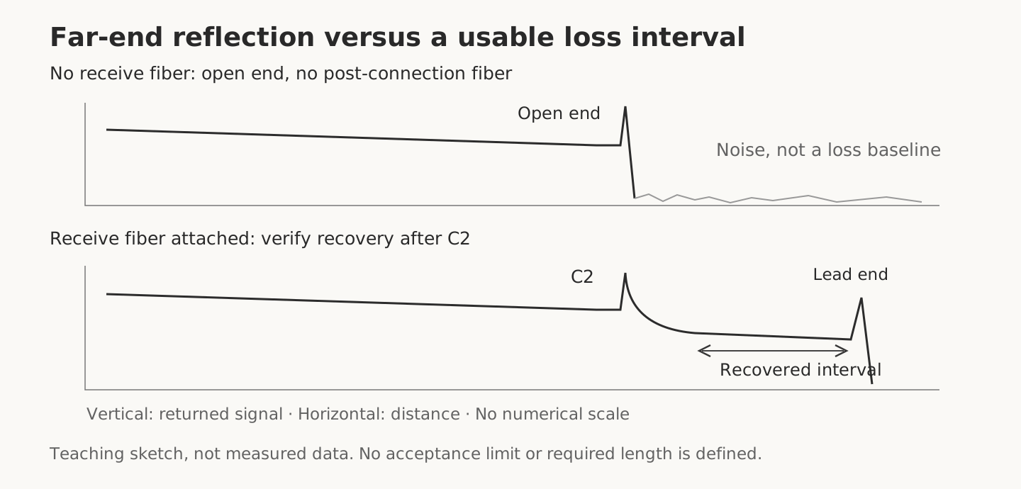 Conceptual traces without a receive fiber and with recovered backscatter after the far-end connectionView original
Original teaching traces, not measured results. The axes have no numerical scale and do not define an acceptance limit or a required lead length.
5. Connector compatibility and extra jumpers
On screen: A short conversion jumper can add another connection to the assessed event.
Instructor notes: EXFO explains that the link-facing termination of the launch lead should suit the ODF connection. Adding a short conversion jumper to a lead with a different connector can introduce additional mated pairs near the ODF. Closely spaced events may not be separately resolved, so a displayed loss can represent more than the one connection originally intended. Apply the same boundary check at the receive side as a DMS interpretation of this measurement principle.
Check polish as well as connector shape. An adapter accepting a plug does not establish that different polish interfaces may safely mate. EXFO describes the extra ODF connection pair introduced by a conversion jumper as undesirable. Prefer a launch lead with the correct ODF termination. If an additional arrangement cannot be avoided, DMS recommends recording it, comparing it with the trace events and not reporting an unresolved combined value as the ODF connection alone. Do not arbitrarily divide the loss of an unresolved group or attribute all of it to one faulty panel connection. Perform endface inspection separately and never look into a connector to check whether a source is active.
6. Hypothetical teaching case
On screen: A missing loss value is not zero loss or a pass.
Instructor notes: In this hypothetical case, a technician uses only a launch lead and saves a peak at the link end. The report has no far-end connection-loss value. The record may help locate the end, but it does not demonstrate that the intended mated connection meets a loss requirement. The reviewer adds a receive lead and checks recovery after the far-end connection, separation from the receive-end event and the link reporting boundary.
Keep the retest as a different record instead of overwriting the original acquisition: the connection and measurement conditions have changed. When a loss value becomes available, verify the boundary and analysis interval before comparing it with the project limit. A usable OTDR assessment of the end connection does not complete the end-to-end insertion-loss test. Testing with an OLTS or a light source and power meter has its own purpose and reference procedure.
7. Field checklist
- Identify the mated connection to assess at each link end.
- Check launch and receive lead identifiers, fiber type, connector type and polish.
- Verify analysis intervals and receive-end separation at the actual pulse width.
- Confirm that reporting boundaries include the link and the intended end connections.
- Prefer a lead with the correct ODF termination; identify extra connections and distinguish combined from individual assessment.
- Save wavelength, pulse width, direction, native trace and any reason for withholding assessment.
8. Check questions and explanations
- Does a far-end reflection peak alone justify a connector-loss pass? No. Configure the intended mated connection and obtain a usable post-event analysis interval.
- A receive lead is attached, but the signal after the connection has not recovered. What should the reviewer do? Withhold assessment and retest with suitable conditions. The presence of the lead alone does not prove measurability.
- Should compensation automatically exclude the last link connection? No. Verify the intended end connections and reporting boundaries against the test objective.
Sources and limits
- EXFO Application Note 298: Martin Warne, APNOTE298.1AN, ©2014, 14/01. Page 1 covers roles, fiber matching, pulse width and termination compatibility; page 2 describes offsets and lead conditions in Figures 2–4.
- VIAVI Launch and Receive Cables: document code 30193711 901 0425, ©2025. Page 1 describes assessment at both ends and matching fiber characteristics. References to standards are manufacturer explanations; the standard texts were not independently verified. Document code and copyright year were checked in the page 2 footer.
- Fluke Networks OTDR Guide: no web edition or publication date stated. Purpose, Test Parameters and Trace Analysis were checked for backscatter, pulse settings and end events.
- Fluke Networks dead-zone explanation: 24 October 2018. Don’t Stay There Too Long was checked for recovery and the two dead-zone definitions.
No source photographs or diagrams were copied. The figures are independently drawn concepts. Product-specific lead lengths, current standard limits, a particular instrument's compensation behavior and physical reproduction remain to be checked. Before working on a live circuit, verify the instrument's permitted optical input, live-fiber capability and work authorization. Do not attach test leads to an operating circuit without those checks.
Next, see the optical field-training curriculum for insertion-loss testing and measurement handover.