Before a splice closure is opened, someone has to decide how much cable sheath to remove. Many crews have heard the rule of thumb that about one metre is enough. If nobody checks where that number came from and which closure it applies to, the cut is already made by the time the question comes up, and a cut cannot be undone.
This lesson does not repeat the bend limits and slack storage already covered in Bend Radius, Slack and Enclosure Discipline. It covers the preparation sequence inside the closure: how far to strip the sheath, where to secure the tubes, how a tray cover can pinch a fiber, and what to check when the closure is opened again. Product figures appear only as examples from that product's own document. They are not acceptance criteria or design-change criteria for any current product.
Learning objectives
- Read cable preparation length from the reference point used in the manufacturer's manual.
- Separate where tubes are secured from where bare fiber is stored in the tray.
- Explain how to check for cover pinching before closing and when re-entering.
Preparation length starts at a reference point
Preparation length is easy to misread when only the word "length" is used. Sheath removal length, strength-member length, the length of tube running to the tray, and the fiber length used for splicing and storage inside the tray are all different quantities. Documents also measure from different starting points. Some measure from where the cable sheath ends. Others measure from a securing bracket.
The Fiber Optic Association (FOA) tells readers to follow the manufacturer's stripping instructions for each closure. In its description, sheath and strength-member lengths serve to secure the cable to the closure, while buffer-tube lengths serve to reach the splice trays so fibers can be spliced and stored. The same page describes a typical loose-tube arrangement: the tubes run from the closure entrance to the tray, where they are secured, and roughly one metre of bare fiber on each side of the splice is organized in the tray after splicing. That is a general description, not a mandatory length that applies to every product.
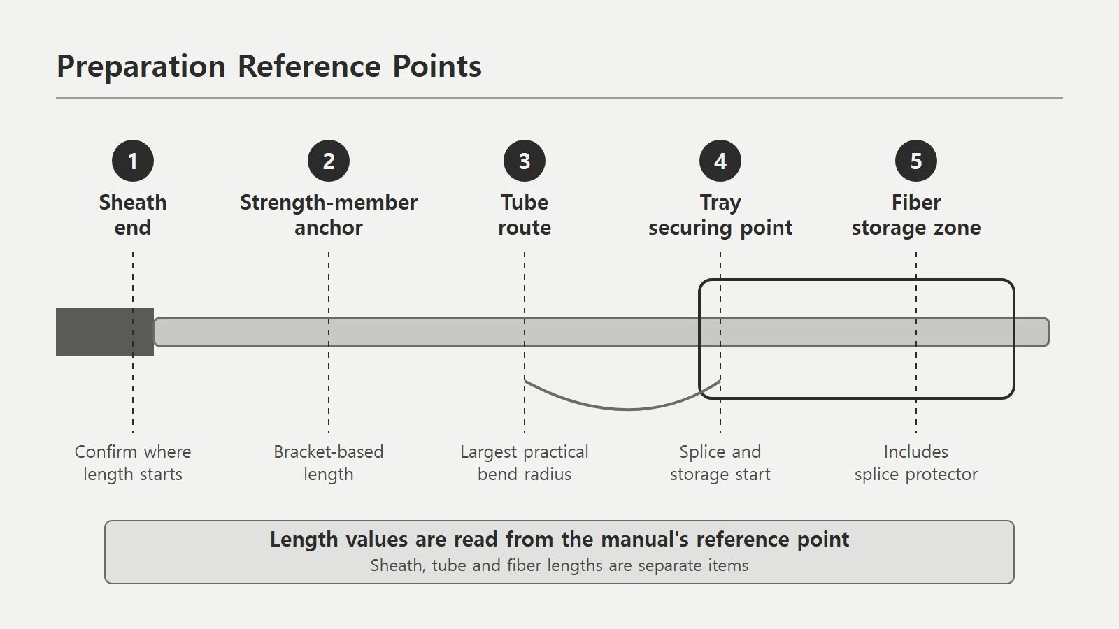 Preparation reference points: sheath end, strength-member anchor, tube route, tray securing point and fiber storage zone shown in orderView original
A DMS concept diagram of the reference points used to read preparation length. It is not a dimensioned or to-scale drawing of any specific product.
Values differ even within one manufacturer
The CommScope FOSC450 C and D installation instructions give cable cut lengths in a table. The values depend on cable type, mid-span or end entry, tray height and slack-basket size. In the table on page 4, loose-buffer-tube cable at an end entry is listed at 43 to 72 in for the C closure and 55 to 75 in for the D closure. Even inside one product family, the suggested storage length changes with closure size.
For mid-span openings with the standard basket, the same table lists 52 to 90 in for the C closure and 102 to 120 in for the D closure. These numbers belong to that document's products and configurations. They must not be carried over to another manufacturer's closure or another cable construction. A note below the table explains that the minimum length assumes the cut goes directly to the tray, while the maximum assumes entry through the basket to the tray. Even within one document, the same number means something different when the route is different.
A 2024 Leviton application note shows the same pattern in another product family. It measures minimum exposed sub-unit length from the exit of the cable jacket to the end of the tubing, and gives 152 cm for SDX splice modules, 203 cm for SDX splice trays and 152 cm for HDX enclosures. The note states separately that these figures do not include extra length removed to eliminate damage from pulling at the cable end, nor the overall slack storage. Trying to collapse all of this into one general number is risky in itself.
Where tubes and fibers are secured
A correct preparation length still causes stress if the securing position is wrong. Per FOA, loose-tube cables have their tubes run from the closure entrance to the tray and secured there. In DMS's reading, the purpose of securing at the tray entrance is to let the fibers enter the splice area smoothly from the tube, with the bare fiber then routed along the tray guides. That is an interpretation of the arrangement, not a quotation of a requirement.
Corning's Standard Recommended Procedure 78-8130-1910-2 (2019) says buffer tubes and transition tubes should keep the largest possible bend radius when routed inside the closure. For ribbon transition applications it shows the transition tube secured to a bracket on the base first, with the other end mounted to the tray after the tray support is in place. This shows why length must be set before securing. After a tube is secured it is hard to adjust, and pulling it to fit puts force on the first bend.
That document describes one manufacturer's procedure. It is not evidence that another closure should follow the same order. Before using a new closure for the first time, FOA advises reading or watching the manufacturer's application notes to learn its sequence. A different sequence gives a different result even with identical parts.
A tray cover can pinch fiber
FOA warns directly that tray covers can pinch fibers and cause breaks. Care is needed so that fibers are not caught when trays are stacked or covers are placed. The same page explains that such a break can be too close to the splice for an OTDR to resolve, so it looks like a bad splice, and that it may be found only with a VFL (visual fault locator). It also notes that fibers are often broken as trays and closures are assembled or re-entered for troubleshooting and repair.
That is why a check before closing matters. Look to confirm the fibers sit inside the guide path, the splice protectors are in their positions, and no fiber protrudes past the cover edge or between trays. If pinching is suspected after closing, a VFL check of the fibers in that tray is one method. A VFL can show the location of a break as a glow of light, but it does not replace measuring loss at the working wavelength. Pass or fail decisions come from separate tests.
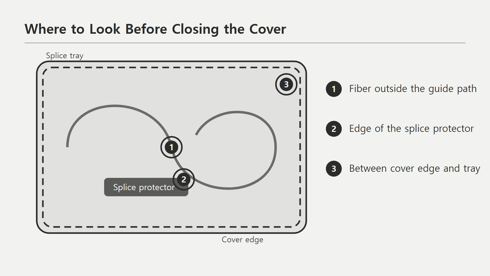 Tray guide path, splice protector and cover edge distinguished, with likely pinch locations marked for the pre-closing checkView original
A DMS concept diagram of the places to inspect by eye before closing the cover. It is not a manufacturer drawing or an approved procedure.
Preparing with re-entry in mind
A closure is not something that is closed once and forgotten. FOA describes dome closures as popular because splicing and service-loop storage are easier to handle, and shows a neater arrangement when re-entering for moves, adds and changes. When tray securing and tube routing have drifted by the time of re-entry, the next technician must verify the whole securing structure, not one or two fibers. Setting the length accurately the first time, recording where things are secured, and checking cover pinching before closing all narrow what the next person has to verify.
A re-entry record should note the closure model, the edition of the manufacturer document used, the sheath removal length, where the tubes were secured and what was checked before closing. These items are a DMS working suggestion. They do not replace a manufacturer standard or a company approval form.
A hypothetical reading exercise
Suppose a technician hears only that one metre is enough and strips the sheath accordingly. The installation instructions for this closure list a separate minimum length for the route that goes directly to the tray. If that value is longer than the technician's length, the tubes either cannot reach the tray entrance or are pulled at the securing point when they do. This is a hypothetical situation created for training. It is not a real customer case or a test result by Reedo, and it does not name a specific product or length.
The first step in this situation is not to cut more. It is to check the document. Confirm that the model applies, whether the opening is mid-span or end entry, and whether the route goes directly to the tray or through the basket. If these are unconfirmed, do not declare pass or fail. Record a request for confirmation.
Cable preparation and tray checklist
The following items are a DMS review suggestion. They do not replace an internal approval procedure or a product acceptance standard.
Scroll horizontally to view a wide table.
| Item to check | What to record |
|---|---|
| Product identification | Closure manufacturer, exact model, cable construction and fiber count |
| Document status | Manual title, edition, applicable model, whether it is an approved source |
| Reference point for length | Whether the value is measured from the sheath end or a securing bracket, and the unit |
| Route | Mid-span or end entry, direct to tray or via basket |
| Securing positions | Strength-member anchor, tube securing point, tray securing point |
| Cover check | Pinching and trapping checked before closing, and whether a VFL check was done if suspected |
| Unconfirmed items | Values not in the document and why the decision was deferred |
On your next job, pick one closure, find the length value in its document and write it down together with its reference point. If the document does not give a reference point, do not invent one. Record it as unconfirmed.
Review questions
1. May the FOA description of about one metre be used as the preparation length for every splice closure?
No. The FOA figure of about one metre is a general description of bare fiber organized in the tray after splicing. Actual sheath removal and tube lengths must follow the manufacturer's instructions.
2. If two closure types come from the same manufacturer, can their preparation lengths be assumed equal?
No. The CommScope FOSC450 C and D table gives different ranges even for the same end entry.
3. After closing a tray cover, loss near a splice looks wrong. If the OTDR shows what appears to be a bad splice, is re-splicing enough?
Suspect cover pinching first. FOA explains that pinch damage can look like a bad splice on an OTDR and may be found only with a VFL.
Sources and further checks
- FOA, Fiber Optic Splice Closures: manufacturer instructions first, tube securing, the approximately one metre description, tray-cover pinching and re-entry. A 2023 copyright notice was confirmed.
- CommScope, FOSC450 C and D Installation Instructions: the cable cut-length table on page 4 and strength-member cut lengths. This is a third-party posting, so check CommScope's official edition before real use.
- Leviton, Application Note NS-AN-18-0030, 2024-04-15: minimum preparation lengths by product family and the items excluded.
- Corning, Standard Recommended Procedure 78-8130-1910-2, Issue 9, 2019-08: bend radius for tube routing and the order for securing transition tubes.
Sources were checked on 5 October 2026. This lesson did not verify specific standard clauses, the latest manuals of currently supplied products, or on-site test results. No photographs or source diagrams are reproduced. Separate concept diagrams were built for explanation.