The loss figure a fusion splicer shows right after a splice is an estimate calculated from camera images, while a one-direction OTDR reading carries a backscatter difference that varies from fiber to fiber, so the two often disagree. The real loss of a splice is found only by averaging OTDR readings taken from both directions. A large one-direction value is therefore not a reason to remake the splice at once; check the opposite direction and the neighboring splices first. In the same way, a low splicer figure is never recorded as a pass on its own.
Based on manufacturer documents reviewed on October 22, 2026.
Learning objectives
-
Separate what a splicer's estimated loss and an OTDR reading are each based on.
-
Set an order of checks when the two disagree and decide from the bidirectional average.
-
Record in the handover that the estimate depends on the splicer's settings and warning functions.
What is the splicer's estimated loss based on?
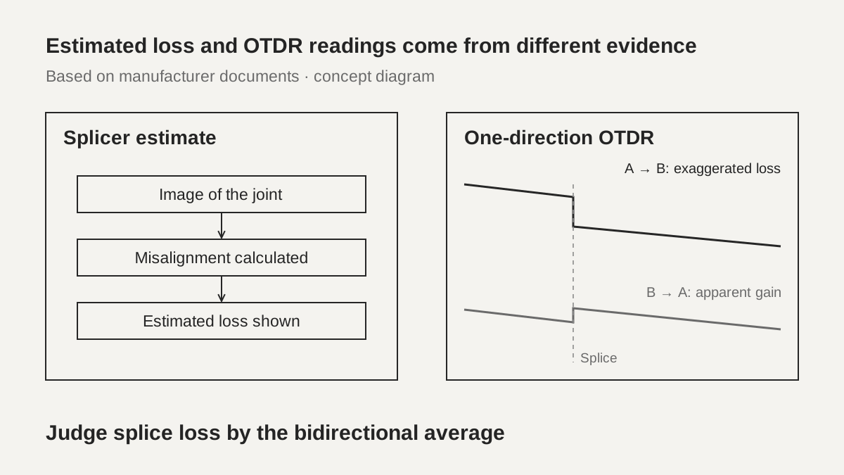
A fusion splicer analyzes images of the two fibers it has joined, calculates how far they are misaligned, and shows the result as an estimated loss. An AFL white paper describes this as an attempt to gauge the power lost at the joint from the image, and notes that splicers differ in both estimation technique and accuracy. A Prysmian (Draka) application note says the same thing in installation terms: during installation the splice loss is estimated by the splicer's image processing, and the splice is approved or rejected on that estimate. The number on the screen is a calculation from an image, not a measurement.
 Estimated loss and OTDR readings come from different evidenceView original
Estimation methods fall into two groups, core alignment and cladding alignment. According to the AFL paper, a core-alignment splicer locates the core centers and estimates loss from how well the two cores line up, while a cladding-alignment splicer cannot locate the core center accurately and relies on the alignment of the outer cladding. In that paper's own test, cladding-alignment estimates skewed toward zero, and it states that an estimate of 0.02 dB is possible with a measured loss of 0.4 dB or more. Note that this is a paper about a Fujikura 41S splicer sold by AFL, that the measurement method is not stated in the text, and that the author says the result does not guarantee performance for every fiber combination or field condition.
Manufacturer manuals take a similar position. The Fujikura 70S manual says an estimated splice loss is displayed when splicing finishes and is calculated from dimensional parameters such as MFD. In its attenuation mode (AT1), which splices with an intentional core offset, the estimate is to be treated as a reference only, may be wrong depending on fiber properties, and a power meter is recommended for a correct splice loss measurement. The copy reviewed is hosted by a reseller and carries no date.
-
The estimate is a value calculated from an image
-
Accuracy depends on the alignment method and mode
-
A low estimate is not a pass decision
Why does a one-direction OTDR reading disagree with the estimate?
An OTDR does not measure splice loss directly; it reads the change in returning backscattered light. Backscatter is inversely proportional to the mode field diameter (MFD), so when fibers with different MFDs are joined, the backscatter level just before and after the splice differs by itself. According to a Corning application note, measuring from the larger-MFD fiber into the smaller one shows a gainer (apparent increase in power), and measuring from the smaller into the larger shows an exaggerated loss. Measuring from the other end flips the sign, so averaging the two directions cancels the difference.
The size of the difference is not small. In a Prysmian example, joining fibers with MFDs of 9.2 µm and 9.0 µm produces a true loss from the MFD difference of only 0.002 dB, yet the one-direction OTDR error is 0.1 dB. In Corning's test the splicer predicted 0.01 dB or lower for every splice and the bidirectional average loss was below 0.05 dB for all of them, but the one-direction values often falsely indicated high loss and showed no correlation with the actual loss over the MFD range tested.
Scroll horizontally to view a wide table.
| Source | What it states | Conditions stated with it |
|---|---|---|
| Prysmian 2010 | MFDs 9.2 and 9.0 µm: true loss 0.002 dB, one-direction error 0.1 dB | Worst-case apparent loss for a 9.0 ± 0.4 µm specification is calculated as 0.39 dB |
| Corning 2014 | Splicer predicted 0.01 dB or lower; bidirectional average below 0.05 dB | Core-alignment splicer, default G.652 program, samples selected for the test |
| Corning 2014 | SMF-28e+ to SMF-28 ULL: about 0.6 dB one-direction, actual maximum 0.035 dB | Pair with an MFD difference under 0.04 µm |
Even fibers of the same type carry a margin of error. Corning's Table 2 gives the probability that a one-direction OTDR estimate lies within ±0.05 dB of the actual loss as 54%, within ±0.10 dB as 78%, within ±0.20 dB as 97%, and lists ±0.30 dB as less than 100%. It adds that splicing different fiber types increases the uncertainty, which covers FTTx work that joins G.652 and G.657 fiber or mixes ultra-low-loss fiber into a link.
-
A one-direction value includes a backscatter difference
-
An apparent gain is often followed by an exaggerated loss
-
Splices between different fiber designs are more uncertain
In what order do you read the two values when they disagree?
The order can be summarized in four steps, and this order is DMS's interpretation. First, confirm the settings that produced the estimate, because without the alignment method, splice mode and loss limit the number has no weight. Next, look at the direction of the OTDR value and at the neighboring splices; if one splice shows an apparent gain and the next shows an exaggerated loss, an MFD or backscatter difference is likely. Then obtain the opposite-direction value and average the two, and finally compare the average with the splice criterion. Setting the criterion on the average rather than on single values is the common direction of these documents.
The reference numbers differ by document and are examples. Corning gives a link average of 0.1 dB per splice as a target and a one-direction estimate above 0.3 dB as the point where further checks begin. Prysmian suggests using a one-direction OTDR for a first analysis but setting a high threshold such as 0.4 dB so that splices that would show as a gainer from the other side are not redone. Both numbers are examples, not contract criteria. Prysmian also points out that OTDR testing usually takes place after closures are closed and buried or mounted, so redoing a splice means travel, traffic protection and setup, and an adequate measurement strategy should be chosen first.
When bidirectional measurement is not possible, Prysmian lists two alternatives, relying on the splicer estimate together with a one-direction check of the average attenuation per kilometer of the link, or using an optical power meter, and says both are less accurate. Corning also allows comparing adjacent splices as a pseudo-average, states that this is not a substitute for bidirectional averaging, and notes that breaking and remaking a splice that shows a gainer is unlikely to change the result. Remaking a splice does not erase a measurement artifact.
Scroll horizontally to view a wide table.
| Situation | How to read it | Next action |
|---|---|---|
| Low estimate, high one-direction OTDR, neighbor with the opposite sign | MFD or backscatter difference suspected | Measure the opposite direction and average |
| Low estimate, high in both directions | Possible real loss that the estimate understated | Check the joint and discuss remaking it |
| Splicer warns of high estimated loss | Possible splice quality problem | Find the cause and remake before closing |
| Bidirectional measurement impossible | High uncertainty | Compare neighbors, use a power meter, record the limit |
-
Settings, direction and neighbors, bidirectional average, average criterion
-
Do not decide a remake from a single one-direction number
-
Reference numbers come from the contract, standard or responsible engineer
What do the estimate warnings and settings change?
Splicer settings control both the estimate and the warnings. The setting table in the Fujikura 70S manual lists an estimation mode (off, cladding, core, core-fine), the MFD of the left and right fibers, a minimum loss that is added to the estimate, a loss limit and a cleave angle limit. With the estimation mode set to off or cladding, the core step, core curve and MFD mismatch corrections are switched off automatically, and the manual says those correction items are advanced functions to be discussed with an authorized distributor before changing. The same model with different settings therefore gives estimates that cannot be compared.
When the loss limit is exceeded an error message appears, and the manual strongly recommends repeating the splice from the beginning if it looks poor on the monitor. An additional arc can reduce loss in some cases, but too many worsen splice strength and loss, so the number can be limited. The listed causes of a high-estimated-loss message are insufficient fiber cleaning, a cleaver with a worn blade, dust on the V-groove and clamp, dust on the lens, worn electrodes, inadequate arc power, an unsuitable splice mode and a loss limit set too low; a cleave limit of 2.0° or less is recommended.
The same manual adds that error messages such as estimated splice loss can be ignored or the function disabled. A splice that never produced a warning may therefore not be a good splice, and this is DMS's interpretation. For that reason the handover records the settings that produced the estimate, not only the estimate itself.
-
Estimation mode, MFD and loss limit shape the number
-
Warning functions can be turned off
-
Start with cleaning, cleaving and electrodes for a high estimate
In the hypothetical case, which splice do you remake?
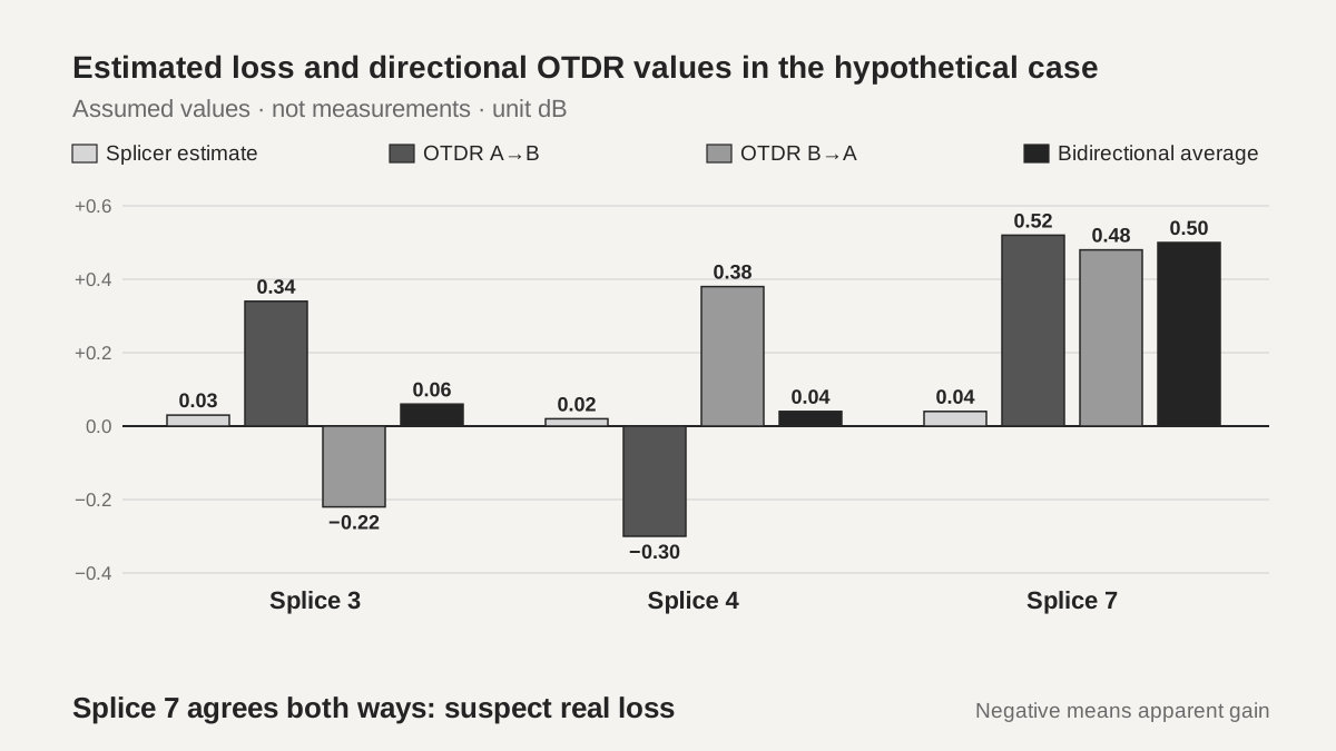
The figures below are assumed for teaching and are not real site or equipment values. Suppose a section with eight splices was checked right after splicing using splicer estimates and bidirectional OTDR values. The splicer warned of a high estimated loss on splice 5, so it was remade before closing and the estimate after remaking was 0.03 dB. Splices 3 and 4 have low estimates, but the A-to-B OTDR shows 0.34 dB for splice 3 and −0.30 dB (an apparent gain) for splice 4. Splice 7 also has an estimate of 0.04 dB, while the OTDR shows about 0.5 dB in both directions.
 Estimated loss and directional OTDR values in the hypothetical caseView original
Scroll horizontally to view a wide table.
| Splice | Splicer estimate (dB) | OTDR A→B / B→A (dB) | Bidirectional average (dB) |
|---|---|---|---|
| 3 | 0.03 | 0.34 / −0.22 | 0.06 |
| 4 | 0.02 | −0.30 / 0.38 | 0.04 |
| 7 | 0.04 | 0.52 / 0.48 | 0.50 |
For splices 3 and 4, adding the opposite-direction value and averaging brings the results down to 0.06 dB and 0.04 dB. Opposite signs on neighboring splices are the typical picture of an MFD or backscatter difference, and remaking those splices would most likely repeat the result and only add cost. Splice 7 agrees in both directions with an average of 0.50 dB, so it is read as a real loss that the estimate understated, and the suggestion to the responsible engineer is to check the joint again. If the other five splices are assumed at 0.03 dB, the average of all eight is about 0.09 dB, within an assumed criterion of 0.10 dB. That the average is inside the criterion and that splice 7 can be left as it is are separate questions, and the responsible engineer and the contract terms decide the second one.
-
Splices 3 and 4: a neighboring pair with opposite signs, average first
-
Splice 7: agreement in both directions suggests real loss
-
Judge the average pass and the individual outlier separately
What goes into the handover record?
For each splice, record the splicer model and software version, splice mode, estimation mode, loss limit and whether warnings were enabled, the estimated loss and the number of additional arcs. On the OTDR side, record the instrument, measurement direction, wavelength, pulse width, index of refraction setting, the value for each direction and the average, plus the fiber type if known. Pulse width and dead zones are covered in the earlier lesson OTDR Dead Zones and Pulse Width. Note whether a neighboring pair with opposite signs appeared, and if the opposite direction could not be measured, say why.
State clearly what was not checked. This lesson did not review the texts of IEC 60793-1-40 or the TIA test procedure, any test run with a splicer by DMS, or the latest revisions from each company. The test conditions of the AFL paper and the edition and date of the Fujikura manual were also not confirmed, and the Prysmian note dates from 2010, the Corning note from 2014 and the AFL paper carries a 2019 copyright. All four documents are manufacturer or sales-related explanations. The original figures and tables were not copied, and the diagrams were redrawn independently.
-
Splicer settings and warning status
-
OTDR direction, wavelength, pulse width, average
-
Write the unchecked scope into the record
Checklist
-
Did you record the alignment method and mode behind the estimated loss?
-
Did you confirm whether the splicer's loss limit and warning functions were enabled?
-
Did you obtain the opposite-direction value instead of deciding a remake from one direction?
-
Did you look for neighboring splices with opposite signs?
-
Did you judge the average criterion and individual outlier splices separately and record both?
Review questions
1. The splicer shows 0.02 dB and a one-direction OTDR reading shows 0.34 dB. Do you remake the splice immediately?
Answer and explanation: No. A one-direction value mixes in MFD and backscatter differences. Check the opposite direction and the neighboring splices, and decide from the bidirectional average.
2. If the splicer's estimated loss is low, may you record the actual splice loss as equally low?
Answer and explanation: No. The estimate is calculated from an image and its accuracy depends on the alignment method and settings. The AFL paper states that a cladding-alignment estimate of 0.02 dB can coincide with a measured loss of 0.4 dB or more.
3. In the hypothetical case, the OTDR shows about 0.5 dB in both directions for splice 7 while the splicer estimate is 0.04 dB. How do you read it?
Answer and explanation: Agreement in both directions makes an MFD difference alone a weak explanation, and the estimate may have understated a real loss. Discuss checking the joint and remaking the splice with the responsible engineer. This case is an assumption for practice reading.
Sources
-
Corning: Guidance for OTDR Assessment of Fusion Spliced Single-mode Fibers (AN3060) · 2014
-
Prysmian (Draka): Single-Mode Fiber Splicing and OTDR splice measurements Application Note · issue date March 2010
-
AFL: Splice Loss Estimation with the Fujikura 41S Fusion Splicer · copyright 2019
-
Fujikura: 70S Fusion Splicer Instruction Manual (reseller-hosted copy) · Rev1, undated, checked 2026-10-22