
Splice protector and tray compatibility cannot be decided from sleeve length alone. Identify the tray kit, splice module and full protector part number, establish single-fiber or ribbon use, then compare the capacity table and its footnotes within the applicable document. Keep an unresolved conflict open rather than filling the gap with an assumed equivalent.
Official CommScope sources checked on 15 October 2026. The main reference is F591 Rev C issue 02, October 2025. F398, bearing code F398.08/07 and a 2016 copyright notice, is a separate comparison source; a supersession relationship was not verified. The review sequence below is a DMS teaching interpretation, not a current standards acceptance limit or a physical assembly test.
Learning objectives
-
Identify the tray, module and protector as separate components.
-
Calculate splice positions and individual fibers in different units.
-
Record conflicts and hold the affected compatibility decision.
Does matching length establish compatibility?
A sleeve may appear to fit an available slot without establishing an approved component combination. The tray shell, retention module and protector are separate identification tasks. This lesson separates a visual fit check from evidence that the manufacturer specifies a combination. Being able to push a component into a holder is not sufficient evidence that it is suitable for use.
Section 3.1 of CommScope F591 separates the module type and quantity, supported splice methods and splice capacity for each tray kit. D-size trays do not all have the same arrangement: SM6, SM12 and SM24 modules appear in different configurations. Start with a label or approved bill of materials identifying the actual kit, and read its complete row rather than treating the tray size as the compatibility decision.
The existing fusion splicing lesson covers the splice-and-protect sequence. Closure cable preparation and tray securing covers preparation lengths and cover pinching. This lesson adds a narrower document check before those tasks. It does not prescribe heater temperatures or times; use the approved procedure for the actual splicer and protector.
Part numbers and dimension references
The official page for 369305-000, SMOUV-1120-01, identifies single-fiber fusion use and lists a length of 61 mm. The separate product 149030-000, SMOUV-1120-R2/12-02-PK, is described for twelve-fiber ribbons and lists 42 mm. These are the values displayed for those specific products. A shorter ribbon protector is not a general high-density substitute for a single-fiber protector.
On page 4, section 6.2 of F591 divides dimensions into outer tubing A, adhesive B and reinforcing rod C. For SMOUV 1120-01-US, the values are 62, 59 and 56 mm respectively. That does not establish why the separate web listing says 61 mm. Neither rounding nor a typographical error was verified. Keep both the exact suffix and the dimension being measured; do not silently equate two identifiers or combine different dimensional references.
The same manual describes a stainless-steel rod for its single-fiber version and a ceramic rod for its ribbon version. This is the manufacturer’s description of that product family, not a universal rule for all protectors. A transparent outer tube does not establish identical internal construction, and a matching length does not authorize substitution between single-fiber and ribbon applications.
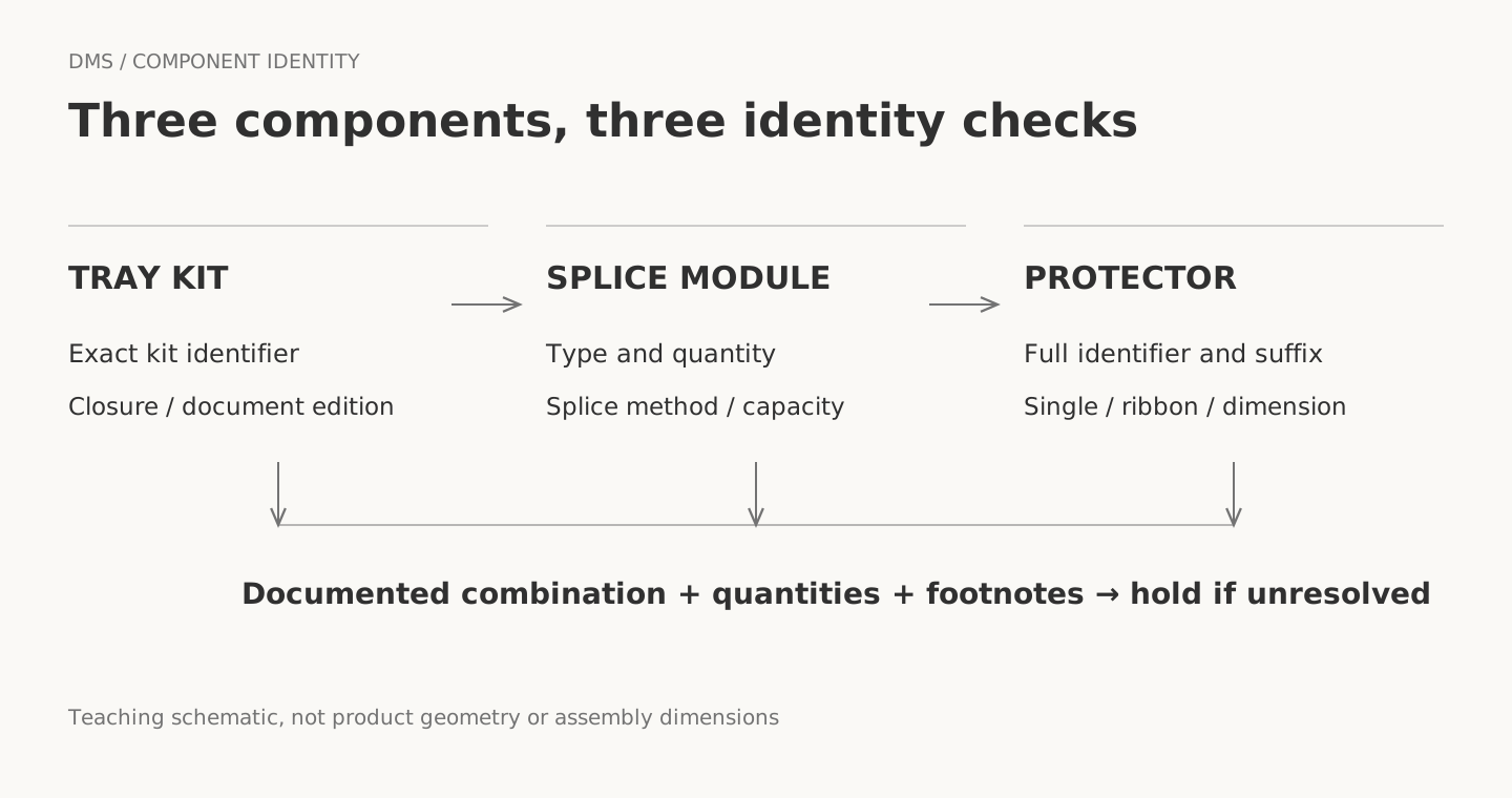 DMS component identity and application check diagramView original
Original teaching diagram, not a product geometry, dimensioned drawing or approved assembly.
Splice positions versus individual fibers
The FOSC-ACC-D-TRAY-SS144-S45 row on page 2 of F591 lists six SM24 modules and 144 single-fiber fusion splices. The module table on the same page lists 24 single-fiber splices for an SM24 module, so six times twenty-four agrees with the tray row. Footnote 3 says that 45 mm SMOUV sleeves required for that application are supplied. It does not, by itself, identify the complete ordering part number of an individual replacement sleeve.
Ribbon counts use a different unit. FOSC-ACC-D-TRAY-RIBN-24 is listed with 24 mass-fusion splices on page 2 of F591. Page 1 of F398 describes the D ribbon tray as twenty-four twelve-fiber ribbon splices, equivalent to 288 individual fibers. Under that condition, 24 is the number of ribbon splice positions, while 288 is the number of fibers served. Comparing 144 single-fiber splices with 288 ribbon fibers as if both were slot counts gives a misleading parts requirement.
Correct arithmetic does not establish the installed capacity by itself. Page 1 of F591 states that actual splice capacity may vary with the slack capacity required, and the detailed table separates kit configurations. Do not transfer a product-family maximum to a specific kit as a guaranteed capacity. Read the exact tray row together with splice method and slack-storage conditions.
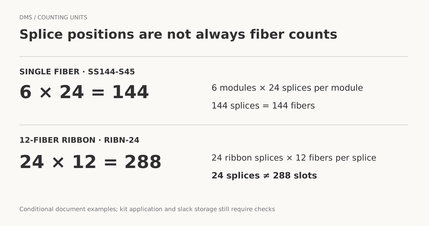 DMS diagram separating single-fiber splice positions from ribbon fiber countsView original
Original teaching diagram, not a product geometry, dimensioned drawing or approved assembly.
What should a conflicting record contain?
When two source values disagree, do not choose the value that makes the job easier. F591 section 3.2 on page 2 lists six single-fiber splices for SM6. Section 6.1 on page 4 lists eight for the SM6 module kit. Both values are visible in the original tables. This lesson does not decide which entry is an error; a decision depending on that SM6 capacity remains unverified.
Handle the web listing of 61 mm and the different-suffix product with 62 mm tubing in the same way. Record the exact identifier, document title, edition, page or web field, value and unit. An official source does not automatically resolve inconsistencies inside or between its documents. A newer publication date is also not a reason to skip product identification and the document’s application scope.
A DMS hold record means that the affected question has not been decided. It is not evidence of equipment failure or a product defect, and it does not prohibit unrelated combinations. Check the actual component identity and applicable documentation, and leave unresolved substitutions within the approved materials decision process. Do not use this lesson to justify machining a slot, forcing a sleeve into place or adding an adhesive.
Hypothetical materials review
In a hypothetical exercise, a technician has an SS144-S45 tray kit and separately purchased sleeves marked 45 mm. The technician wants to approve the replacement because the lengths match. This is a teaching example, not a DMS customer case or test result. Record the tray footnote and the complete sleeve identifier first, then compare the single-fiber or ribbon application and the intended module.
A statement that the kit requires 45 mm sleeves is different from evidence that the sleeve in hand is the specified part. Without support for the separate component, mark the combination unverified. A low optical loss result would not close that documentation gap. Optical performance evidence and suitability of the mechanical protection components need their own records.
Review sequence and handover
The purpose of a check sheet is to let the next person reproduce the decision, not to copy a long product description. Keep the tray kit, module quantity and sleeve part number together as a component combination. State whether the application is single fiber or a ribbon with an identified fiber count. Record document edition and page, and separate splice positions from individual fibers. Do not replace an empty field with an assumed default.
For storage, follow the applicable manufacturer instructions and company-approved practices. Section 5 of F591 calls for protecting and strain-relieving fusion splices with sleeves or similar approved devices, and says silicone or similar compounds are not necessary to secure fibers in the holders described there. Do not turn that statement into a universal adhesive prohibition for other trays. On the next job, trace one component combination from identifiers to quantity units and check that an unverified field has not been entered as passed.
Compatibility check sheet
Scroll horizontally to view a wide table.
| Check | Record |
|---|---|
| Component identity | Full tray, module and sleeve identifiers, including suffixes |
| Application | Single fiber or ribbon fiber count; applicable closure |
| Quantity | Module count, splice positions and fibers in separate fields |
| Evidence | Document title, edition, page, footnote and dimension reference |
| Conflict | Both values and the scope of the held decision |
| Handover | Reviewer, date and remaining approval items |
Review questions
1. Does a matching 45 mm label authorize a replacement sleeve?
No. Confirm the full part number, application and evidence for the module combination.
2. Do 24 twelve-fiber ribbon splices mean 288 splice positions?
No. There are 24 ribbon splices and, under that condition, 288 individual fibers.
3. May the larger of the two SM6 capacity values be selected?
No. Record the source conflict and hold the affected capacity decision.
Sources and limits
-
CommScope F591, Rev C issue 02, October 2025: pp.1–4, §§3.1, 3.2, 5, 6.1, 6.2.
-
CommScope F398, code F398.08/07; copyright 2016: pp.1–2, 4.
-
CommScope 369305-000, SMOUV-1120-01: single fusion, 61 mm.
-
CommScope 149030-000, SMOUV-1120-R2/12-02-PK: mass fusion, 42 mm.
All sources are from one manufacturer, not independent standards validations. Web pages did not identify an edition or publication date; the check date is stated above. Current supplied-part identity, substitution approval, current standards and physical fit remain unverified. No source photographs or diagrams are reproduced.
Next lesson
Next: DMS optical training curriculum connects this component review with splice protection, tray storage and measurement lessons.