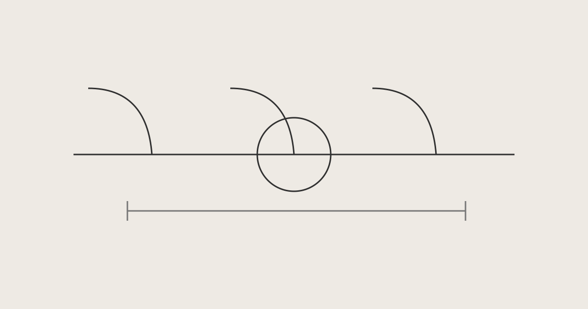
Read reflectance and optical return loss by checking both the sign and the object being measured. For the same connection and reference plane, their defining power ratios have opposite signs in decibels. That does not make one connector’s reflectance the optical return loss of an entire fiber span. Match the quantity, region, reference plane and wavelength before comparing results.
This lesson uses official Fluke Networks web material and a VIAVI application note carrying a 2019 copyright, checked on October 16, 2026. The calculations are DMS teaching interpretations for passive optical components. They are not verified current standard limits, project acceptance requirements or a demonstration of a current instrument interface.
Learning objectives
-
Distinguish the ratios and signs used for reflection.
-
Separate an event result from a region result.
-
Record comparable conditions and unresolved items.
Opposite signs, identical result?
Reflectance is ten times the base-ten logarithm of reflected optical power divided by incident optical power. Return loss reverses that ratio. For a passive component, the first is normally negative and the second positive under these definitions. Both use dB. Treating a smaller number as better for every dB field reverses the comparison for return loss.
For a hypothetical connection, let reflected power be one hundred-thousandth of incident power. Its reflectance is -50 dB and its return loss is +50 dB. These describe the same power ratio in opposite ways. They are not measurements, product guarantees or a universal connector acceptance limit.
For the same object under matching conditions, reflectance of -60 dB means a smaller reflected fraction than -40 dB. With positive return-loss notation, +60 dB means a smaller reflected fraction than +40 dB. Relative reflection performance is separate from compliance. Without an applicable specification and valid measurement conditions, explain the direction of the comparison, not a pass verdict.
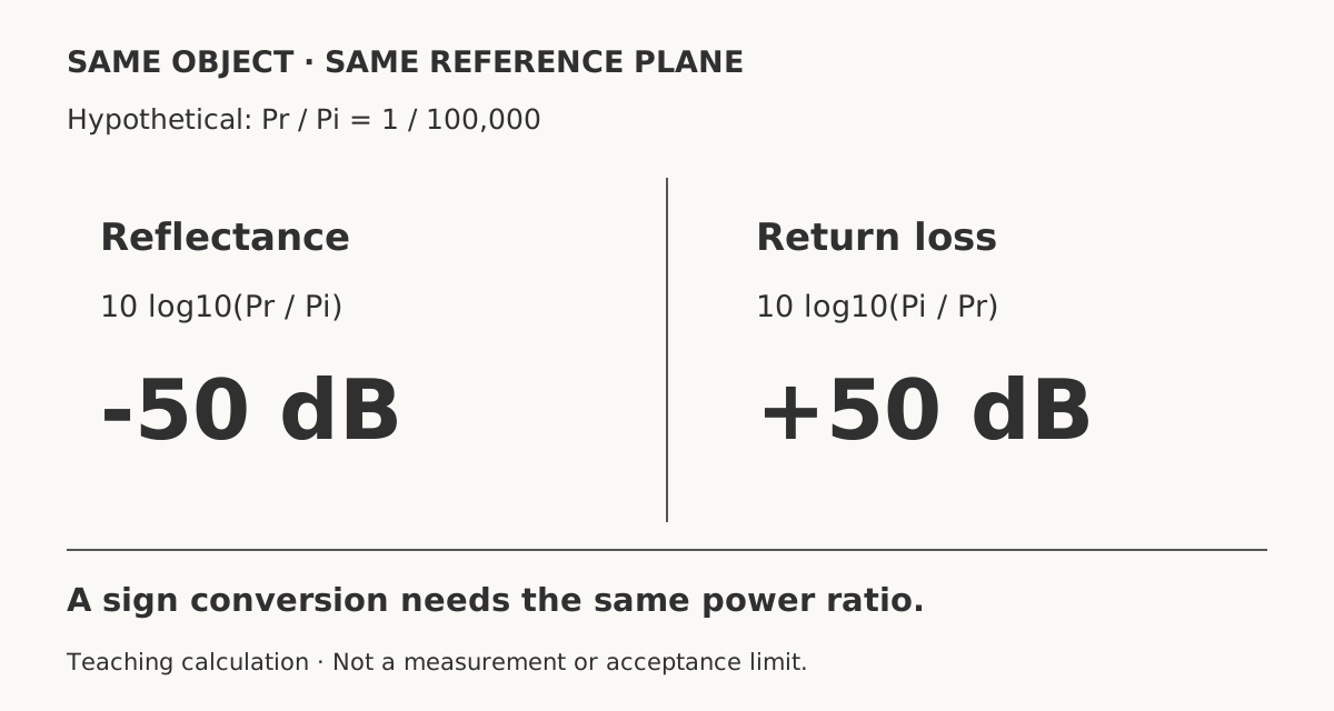 Reflectance and return loss signs for the same objectView original
Original DMS teaching diagram, not an instrument screen, acquired trace or acceptance limit.
One event versus a fiber region
An optical time-domain reflectometer, or OTDR, can report reflectance for individual events. Span optical return loss, or ORL, includes the returned contribution of multiple reflections and fiber backscatter within a defined region. One connector and an entire span therefore have different measurement scopes. A connector result of -50 dB does not automatically establish a span ORL of 50 dB.
A component supplier may specify one connection using positive return loss, while some documents use reflection terminology loosely. Do not repair a sign merely because of the field name. Check the defining ratio and the object in the source. Keep the original result and, if you normalize notation for comparison, record the conversion and the evidence that the object and reference plane are the same.
The first page of the VIAVI note describes ORL in terms of launched light and returned light from a defined length or region, making length an important condition. Fluke’s span description also includes reflections and fiber backscatter. Together they show why an ORL number without region boundaries cannot establish that two reports evaluated the same optical span.
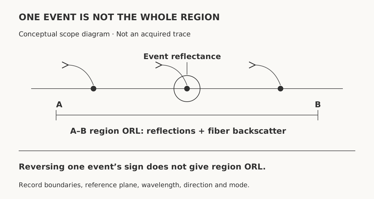 One event versus a region ORL measurementView original
Original DMS teaching diagram, not an instrument screen, acquired trace or acceptance limit.
Conditions to align before comparison
Begin the comparison record with an event number and distance, or with the start and end of a region. Add the reference plane, meaning the location at which the power ratio is referenced, then the test direction and wavelength. Record whether launch and receive cords are included in the evaluated region. A cord being physically connected does not prove that it is part of the reported calculation.
When comparing ORL techniques, match the measurement mode too. VIAVI compares optical continuous-wave reflectometry, or OCWR, with a time-domain technique. Its time-domain system distinguishes a discrete-reflection mode from an integral-region mode. The first searches for a reflective event in a window, while the second sums returned optical power over a window. Those are descriptions of the cited VIAVI system, not menu names guaranteed on every tester.
The same note explains conditions for equivalent measurements between the techniques, including matching the time-domain window to the region defined by actual fiber length in the OCWR setup. Moving or widening a window can change the backscatter and reflections included. This lesson does not turn a device-specific window length into a universal setting. Check the mode, window and reference plane required by the instrument instructions and approved test procedure.
Does a missing result mean no reflection?
A blank reflectance field or a measurement-range indication is not proof that reflected power is absent. Fluke’s OptiFiber note explains that receiver saturation from a strong reflection and noise masking a weak reflection limit the measurable range. Separate an unresolved reading from a valid measurement of a small reflected fraction.
The same document explains that ORL can also be limited when part of the signal saturates or when the entire trace has not been captured adequately. Low insertion loss or a clean end-face image does not establish a valid reflection result. Preserve the original trace, selected region and instrument warnings, and hold the affected reflection verdict if measurement limitations remain.
Do not look into an operating optical port to investigate a reflection result. Connections to live plant and the use of a test source must follow the equipment safety instructions and site authorization procedure. This lesson does not claim that a basic optical power meter performs every reflection test, nor does it establish calibration requirements or receiver saturation limits.
Hypothetical report review and handover
In a hypothetical exercise, report A lists event 3 at -50 dB reflectance, and report B lists 35 dB region ORL. Neither value is a field measurement. They refer to different objects, so their numerical difference is not a connector defect magnitude. Compare direction, wavelength and the region definition first; keep the direct comparison unresolved until the required conditions have been established.
In a separate hypothetical component requirement, suppose the same connection at the same reference plane must have return loss of at least 45 dB. A valid reflectance measurement of -50 dB for that connection may then be expressed as +50 dB for comparison with that reflection requirement alone. This is not a real delivery requirement and does not demonstrate whole-link acceptance, insertion-loss compliance or the suitability of every connector.
Keep the original field name and sign in the handover, with the normalized definition and scope beside them. Connect the raw file to an event number or region boundaries, direction and wavelength rather than copying a standalone number. For today’s work check one report for a connector reflectance value that has accidentally been entered as whole-span ORL.
Report checklist
Scroll horizontally to view a wide table.
| Item | Record |
|---|---|
| Quantity | Original name, definition, unit and sign |
| Scope | Event ID/distance or region start/end |
| Conditions | Reference plane, direction, wavelength and cord inclusion |
| Method and validity | Instrument/version, mode, window, saturation/noise warnings |
| Verdict basis | Approved specification, edition and applicable limit |
| Handover | Raw file, conversion, unresolved items and check date |
Review questions
1. Which reflects less light: -60 dB or -40 dB?
For the same object and conditions, -60 dB. Compliance still requires an applicable specification.
2. May event reflectance of -50 dB be recorded as span ORL of 50 dB?
No. Sign reversal applies only to the same object and reference plane, not from one event to a whole span.
3. Does a missing reflectance value establish no reflection?
No. Check range, saturation, noise and warnings, and hold an unresolved verdict.
Sources and limits
-
Fluke Networks: Reflectance and Optical Return Loss (ORL) Measurement and Testing - OptiFiber
-
VIAVI: Comparing Optical Return Loss (ORL) Measurement Methods
The VIAVI note carries ©2019 and document code 30173337 000 1012; definitions, modes and comparison conditions are on pages 1–6. The OptiFiber note is historical product material discussing software 1.8 onward. The web bodies do not clearly state publication dates or editions. Current standard clauses, actual instruments and delivery acceptance limits were not verified. Source photos and diagrams were not reproduced, and product settings or limits are not generalized.
Next steps
Use OTDR far-end connector evidence to separate an observed end reflection from a loss verdict, and connector inspection handover to connect images with test records. Continue with the DMS optical training curriculum.