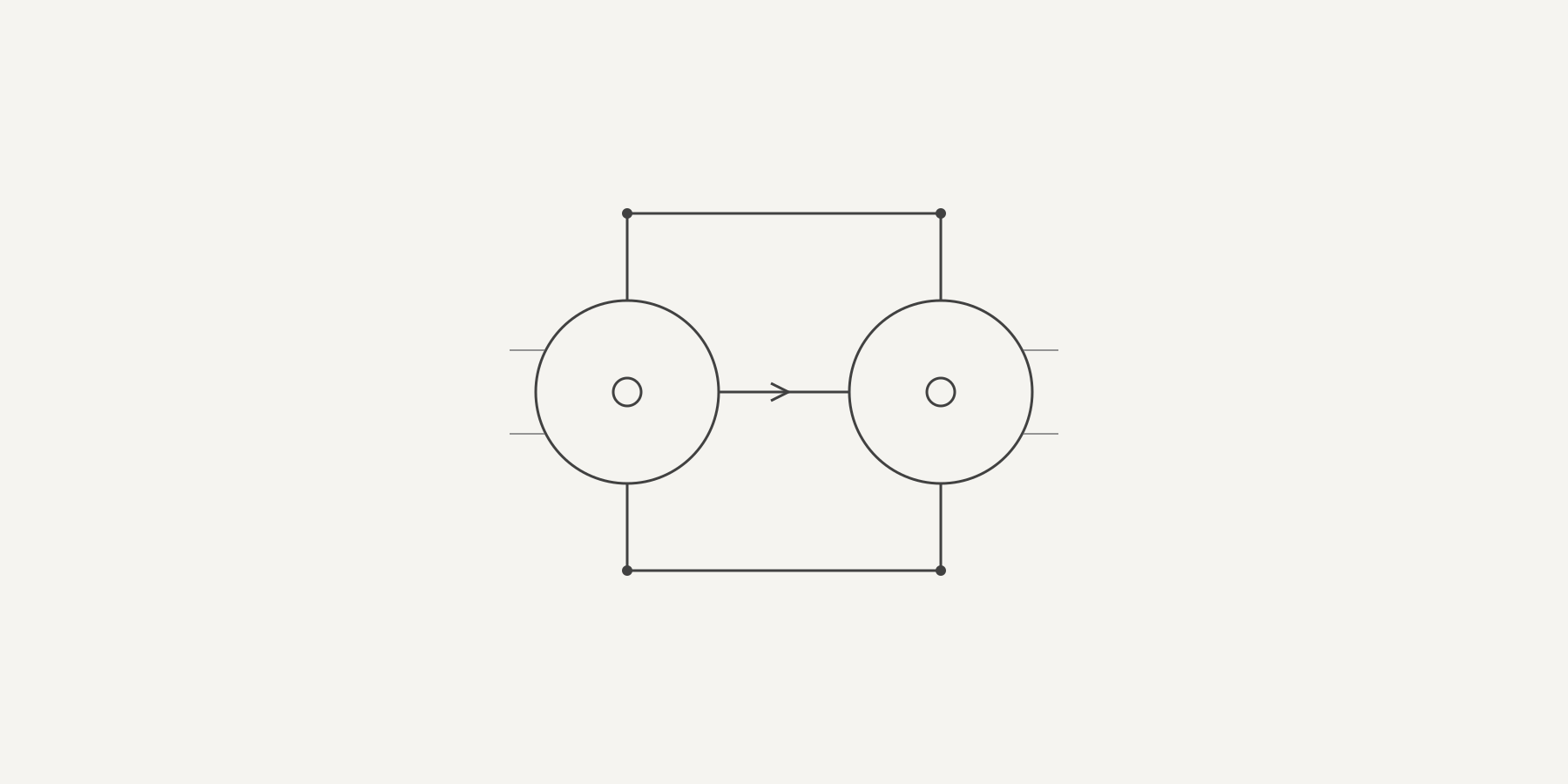
A fiber inspection handover needs more than a pass symbol. Save enough information to identify the inspected face, the selected inspection limit and the capture time, then link those records to the optical tests for the same fiber. Identify the plug and the opposing face inside the port separately. An endface inspection pass is not a pass for the optical loss of the entire link.
The official Fluke Networks sources were checked on 12 October 2026. The instrument example uses the FI-3000 Users Manual, March 2019, Rev. 1 7/2019. This is not a claim that the current application has identical menus. Check the manual for the equipment actually in use and the project specification first. The handover table and record-linking method below are DMS teaching recommendations, not mandatory fields defined by IEC.
Learning objectives
- Distinguish two mating faces from the two ends of a cable.
- Separate limit-based results from documentation-only images.
- Prepare records that another person can open and identify.
1. A result screen and a handover record
On screen: Attach identity and inspection conditions to the image.
Instructor notes: Inspecting a face and handing over evidence are different tasks. A clear image seen during work is difficult to retrieve later if the saved record has no port identity. A correct name is equally unhelpful if the image is unreadable. The receiving engineer needs to know where the image was captured, what was inspected and which limit was applied without relying on the original technician's memory.
The Fluke Networks white paper describes keeping inspection images and pass/fail results alongside loss or OTDR records. Saving an image does not, by itself, preserve the conditions of an optical measurement. Endface inspection, insertion-loss measurement and OTDR testing answer different questions. Keep their results and settings separate, and connect them through the fiber identity rather than collapsing them into one pass entry.
The existing connector contamination lesson explains basic inspection and cleaning. The test documentation lesson covers measurement settings and original test files. This supplementary lesson focuses on keeping endface evidence attached to the correct physical object, rather than repeating the cleaning procedure. Those existing lessons are in English at the linked curriculum routes.
2. What does both sides mean?
On screen: Plug versus port is different from cable end A versus B.
Instructor notes: At a single connection, inspect the patch-cord plug face and its opposing face inside the adapter or equipment port separately. Both sides refers here to the faces that will mate. Photographing cable ends A and B at opposite ends of a route does not show both mating faces at either connection. Begin the handover record with location and port, then identify the component face within that location.
On printed page 12 of the FI-3000 manual, End 1/End 2 is a setting selected when saving a result to specify which end of the cable was tested. Do not redefine those labels to mean plug and internal port face. If the instrument does not offer a separate field for the mating component, use an additional handover-table column or an approved identifier convention. Do not assume a field or feature exists merely because it would be useful.
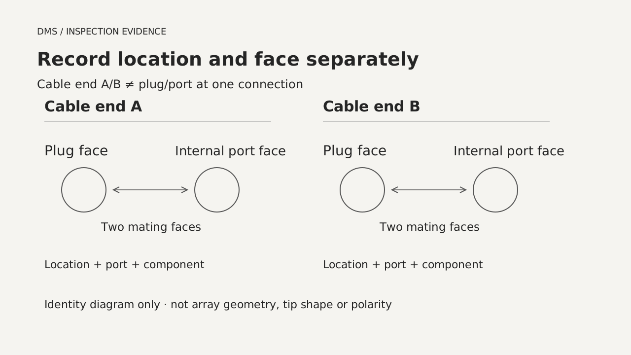 Cable ends A and B, each with a separately identified plug face and internal port faceView original
An explanatory identity diagram, not an instrument screen or a site photograph. It does not represent tip geometry or fiber-array orientation.
3. Inspection limits and documentation only
On screen: An unknown limit or documentation-only image is not a pass.
Instructor notes: The FI-3000 manual describes selecting the correct Test Limit for the job and the Fiber End Type with the correct number of fibers in the project settings. Before saving, check that the selected limit and end type match the actual inspection target. A familiar profile name is not sufficient evidence of compliance with a project specification. Compare the connector, fiber type and array with the instructions for the equipment in use.
Printed page 6 states that a Document Only result has no Pass or Fail status. Image documentation and automatic grading against a limit are different operations. Naming a documentation-only image as a pass can imply a judgment that the technician did not make. If a separate judgment is required, establish the applicable criterion and the person making that judgment, then record it explicitly rather than changing the meaning of the saved image.
A profile name alone may not establish the edition of a standard. Record the instrument model, the software version that can be verified, and the selected profile name. If these details are absent from an exported report, retain them in a separate conditions sheet. This lesson does not verify the limits or clauses in the current IEC 61300-3-35 text and therefore gives no numerical defect-size or defect-count acceptance criteria.
Scroll horizontally to view a wide table.
| Record state | Information to hand over | Avoid |
|---|---|---|
| Limit-based instrument pass or fail | Selected limit, target, image and instrument result | Entire link passed |
| Document Only | Image, target and documentation-only label | Inspection passed |
| Unverified limit or target | Missing conditions and responsible reviewer | Verification complete |
4. MPO fiber numbering and orientation
On screen: Check image numbering against physical fiber numbering.
Instructor notes: An MPO face contains multiple fibers, so the receiving engineer needs to retrieve the result for a particular fiber as well as the overall result. Printed page 13 explains that the FI-3000 Key Position setting must account for the inspection-tip key position and adapter type for image numbers to agree with connector numbers. Numbering fibers from the left side of a displayed image is not an adequate substitute for that check.
This is a procedure for the stated instrument, tip and adapter combination. It is not a universal rule for other inspection-camera displays or for determining the polarity of an installed link. Record the tip, adapter and the basis used to establish the numbering, then associate the selected fiber result with its physical port. If numbering remains uncertain, a sharp image is still not definitive evidence for the claimed individual fiber.
5. Save, export and reopen
On screen: Reopen the exported file and check that it remains readable.
Instructor notes: Printed pages 15 and 17 describe saving from the FI-3000 result summary and detailed-image screens. Pages 20–21 describe exporting saved results as an endface image or PDF report. These are descriptions of available functions, not permission to email customer records or upload them to a public account. Follow the approved internal storage location and the access permissions for the actual records.
After export, verify both the filename and the contents. The manual warns that images shared from some Android devices may have lower resolution than the probe images. File creation is therefore not evidence that the exported image is adequate. At the scale the recipient will use, check whether the face, fiber number, result and required limit information are readable. Keep the original saved result when an export loses detail, and supplement it through an appropriate export method or a separate conditions sheet.
DMS recommends a linking key comprising location, panel, port, cable ID, fiber number, cable end, mating component and inspection time. Align the FI-3000 Cable ID with the identifiers used for the actual plant. These fields need not all appear in a single long filename. Use a short, useful identifier in the filename and connect image, report and optical-test paths in the handover table. Preserve earlier results when a correction or reinspection occurs, and record the reason and new capture time so the final result is identifiable without erasing its history.
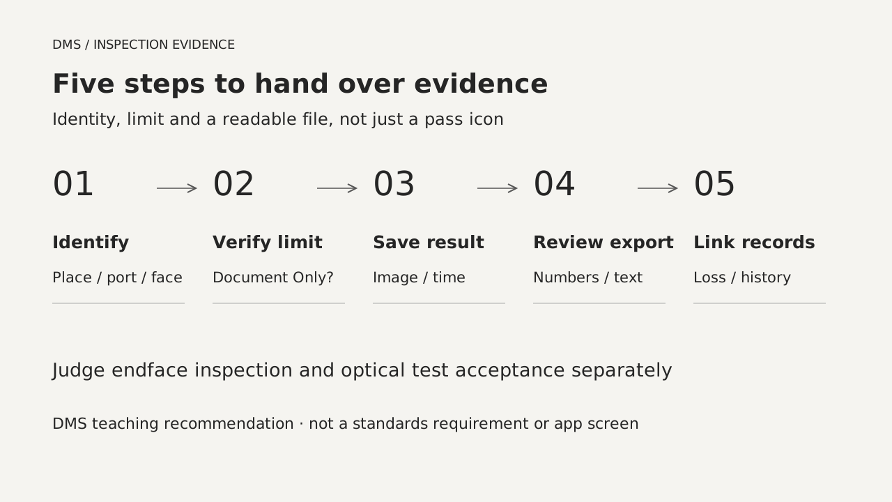 Five stages from target identification to limit verification, saved inspection, export review and handover linkageView original
An original DMS teaching workflow, not a mandatory standards sequence or a representation of actual application menus.
6. Hypothetical handover exercise
On screen: Check the identity and conditions, not merely the image count.
Instructor notes: In this hypothetical exercise, a technician inspects port 07 on panel P1. One file shows a pass but omits the mating-component identity. Another image has only a port name. Before treating the two files as opposing faces at that connection, establish what each image actually captured. If the original target is unknown, do not rename the file by guesswork and present the target as verified.
If the second image was saved under Document Only, retain that status. Placing an automatically graded image beside a documentation-only image does not complete the inspection evidence for the connection. Resolve the target and limit information, reinspect any required face, and record the new time and result. Link optical tests using the same fiber identifier, while reviewing optical acceptance against those tests' own settings and specifications. This exercise is not a customer case or a claim of work performed by DMS.
7. Handover checklist
- Do location, panel and port identifiers agree with the drawings and fiber records?
- Are cable end and mating component recorded as different fields?
- Is each opposing-face image linked to the object actually inspected?
- Are the selected limit, end type, instrument and verifiable software version recorded?
- Has MPO numbering been checked using the applicable instrument manual?
- Are documentation-only records separated from pass/fail results?
- Are the required image details and text readable after export?
- Can the recipient find optical-test records, reinspection history and the final result for the same fiber?
8. Check questions
- Does one image from cable end A and one from end B prove that both mating faces at a connection were inspected?
- Answer: No. Cable ends and the opposing plug and internal port faces are different distinctions.
- Can an FI-3000 Document Only result be handed over as an automatic inspection pass?
- Answer: No. That mode has no Pass or Fail status; label it as documentation only.
- What is missing if an MPO image and pass symbol are clear but numbering orientation is unknown?
- Answer: Verify the applicable tip, adapter, key setting and physical fiber-number mapping. Do not infer the numbering from the displayed image alone.
Sources and limitations
- Fluke Networks, FI-3000 Users Manual, March 2019, Rev. 1 7/2019: printed pages 4 (optical safety), 6 (Document Only), 12 (project and identity), 13 (numbering), 15–18 (inspection and images), 20–21 (export and resolution). Add two to the printed page number to locate the corresponding PDF file page.
- Fluke Networks, Fiber Contamination, Cleaning and Inspection white paper: Inspecting for Assurance; Grading and Certification via Standards; Knowing What to Inspect and Clean. The web edition has no verified publication date or version label.
- Instrument procedures are verified manufacturer descriptions. The handover table and linking key are DMS interpretations. Both sources come from one manufacturer and are not two independent standards verifications. No source photographs, diagrams or application screens are reproduced.
- Never look directly into an optical connector. Invisible optical radiation may be present; follow site optical-safety procedures and the instrument manual. This lesson provides neither a physical equipment test nor validation of current application behavior.
Next lesson
Use the DMS fiber training curriculum to continue with optical measurement and fault response. The Korean version covers the same scope and limitations.