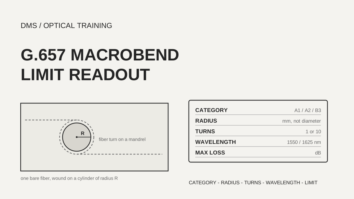
On a bend-insensitive fiber datasheet, the macrobend limit is one line made of four values: mandrel radius (mm), number of turns, wavelength (nm) and maximum added loss (dB). In the documents reviewed, that limit describes a single bare fiber wound on a cylinder before it goes into any cable, and if the radius, the turns or the wavelength differ, two sheets cannot be compared directly. For example, at a 10 mm radius with one turn at 1550 nm, the G.657.A1 limit is 0.75 dB and the G.657.A2 limit is 0.1 dB, a factor of 7.5. So copy the four values before you trust the category name, and check them against the guide radius of the tray or closure.
As of November 8, 2026, based on the documents listed under Sources.
Learning objectives
-
Read the four values of a macrobend line (radius, turns, wavelength, maximum added loss) separately.
-
Check the G.657.A1, A2 and B3 limits against a manufacturer sheet line by line, and calculate how much the allowed loss grows as the radius shrinks.
-
Explain why a datasheet limit describes one bare fiber and why installation acceptance needs its own criteria.
What values does one macrobend line contain?
ITU-T G.657 (August 2024 edition) states that macrobending loss in uncabled fibre varies with wavelength, bending radius and the number of turns around a mandrel, and that it shall not exceed the maximum in the tables. The Recommendation says a specification at one single radius is no longer sufficient, so limits are given at several radii. It also says that because bending loss increases with wavelength, a limit at the highest envisioned wavelength, either 1550 nm or 1625 nm, suffices. It names the mandrel winding method (method A of IEC 60793-1-47) for measurement, but that standard's text was not read for this lesson.
The minimum design radius differs by category. G.657.A1 is appropriate for 10 mm, G.657.A2 for 7.5 mm and G.657.B3 for 5 mm. Category A is a subset of G.652.D and is suitable throughout 1260 nm to 1625 nm, so it can be used wherever G.652.D is specified. Category B is meant for short reaches of less than 1000 m inside or near buildings, and its chromatic dispersion and PMD (polarization mode dispersion) need not match G.652.D. The 2024 edition has no B2. A note under the B3 table says the earlier B2 had the same macrobending requirement as A2.
The table below copies only the macrobend rows of Table 1 and Table 2 in the 2024 edition. Each cell shows the 1550 nm limit then the 1625 nm limit, in dB.
Scroll horizontally to view a wide table.
| Radius × turns | G.657.A1 (1550 / 1625 nm) | G.657.A2 (1550 / 1625 nm) | G.657.B3 (1550 / 1625 nm) |
|---|---|---|---|
| 15 mm × 10 turns | 0.25 / 1.0 | 0.03 / 0.1 | no row |
| 10 mm × 1 turn | 0.75 / 1.5 | 0.1 / 0.2 | 0.03 / 0.1 |
| 7.5 mm × 1 turn | no row | 0.5 / 1.0 | 0.08 / 0.25 |
| 5 mm × 1 turn | no row | no row | 0.15 / 0.45 |
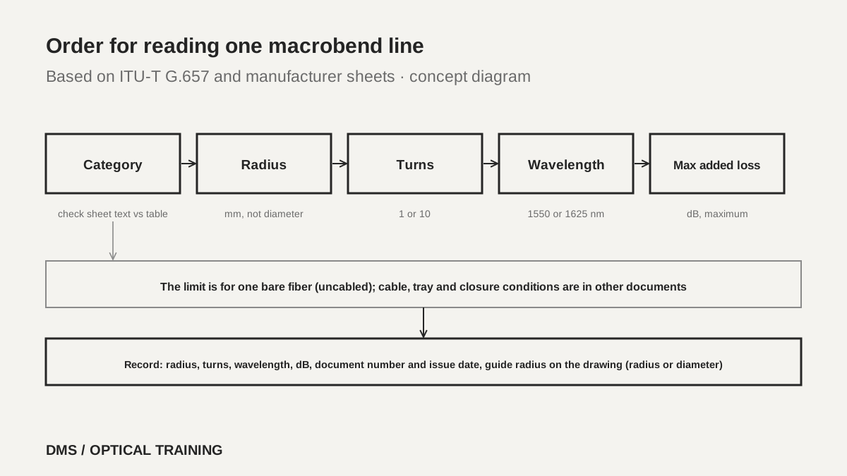 Order for reading one macrobend lineView original
-
The radius is the mandrel radius, not the diameter
-
A one-turn limit and a ten-turn limit use different turn counts, so do not compare them directly
-
An empty cell means no specification exists for that condition, not a limit of zero
How do manufacturer sheet lines match the Recommendation limits?
The North American Prysmian sheets for BendBright A2 and BendBright XS (December 2025) list 0.5 dB at 1550 nm and 1.0 dB at 1625 nm for one turn at 7.5 mm, 0.1 dB and 0.2 dB for one turn at 10 mm, and 0.03 dB and 0.1 dB for ten turns at 15 mm. These are the same numbers as the G.657.A2 column. The two European Prysmian sheets (November 2023 for A2, November 2025 for XS) list the same six lines. Corning SMF-28 Ultra (PI1424, July 2025) says its bend performance exceeds G.657.A1 and lists 0.50 dB at 1550 nm and 1.5 dB at 1625 nm for one turn at 10 mm, 0.05 dB and 0.30 dB for ten turns at 15 mm, and 0.1 dB at 1625 nm for 100 turns at 30 mm. Against the A1 limit, the 1550 nm value at 10 mm falls from 0.75 dB to 0.50 dB, while the 1625 nm value of 1.5 dB is the same. Corning ClearCurve ZBL (PI1464, June 2023) says it exceeds G.657.B3 and lists 0.10 dB at 1550 nm and 0.30 dB at 1625 nm for one turn at 5 mm, below the B3 limits of 0.15 dB and 0.45 dB at that radius, but that sheet has no 10 mm or 7.5 mm line.
In DMS's reading, a sheet value that is lower than a category limit at the same radius and turns does not by itself show that the fiber meets a higher category. Corning SMF-28 Ultra at 10 mm, one turn, 1550 nm lists 0.50 dB, below the A1 limit but five times the A2 limit of 0.1 dB, and the sheet says it exceeds A1, not A2. Confirm the category from the sentence the sheet itself prints, and check the table numbers against the same condition in the Recommendation, one line at a time.
Scroll horizontally to view a wide table.
| Document and edition | Category the sheet states | Macrobend lines (1550 / 1625 nm, dB) | MFD at 1310 nm (µm) |
|---|---|---|---|
| Corning SMF-28 Ultra PI1424 (July 2025) | exceeds G.657.A1 | 10 mm×1: ≤0.50 / ≤1.5 · 15 mm×10: ≤0.05 / ≤0.30 · 30 mm×100: 1625 nm ≤0.1 | 9.2 ± 0.4 |
| Corning ClearCurve ZBL PI1464 (June 2023) | exceeds G.657.B3 | 5 mm×1: ≤0.10 / ≤0.30 | 8.6 ± 0.4 |
| Prysmian BendBright A2 North America TLS-DS-F-004-1225 (December 2025) | A1 and A2 both appear in the header | 7.5 mm×1: ≤0.5 / ≤1.0 · 10 mm×1: ≤0.1 / ≤0.2 · 15 mm×10: ≤0.03 / ≤0.1 | 9.2 ± 0.4 |
| Prysmian BendBright XS North America TLS-DS-F-005-1225 (December 2025) | G.657.A2 | the same six lines | 8.8 ± 0.4 |
| Prysmian BendBright A2 Europe (November 2023) | G.657.A2 | the same six lines | 9.0 ± 0.4 |
| Prysmian BendBright XS Europe (November 2025, 160 µm coating) | G.657.A2 | the same six lines | 8.8 ± 0.4 |
How much does the allowed loss grow as the radius shrinks?
Note 2 of the Recommendation says that if a number of turns other than the one in the table is chosen, the maximum loss is assumed to be proportional to the number of turns. Borrowing that assumption and dividing each limit by its turns shows how fast the allowed loss grows as the radius falls. This is DMS's calculation applied to limit values. It is not a measured loss, and the Recommendation does not prescribe this conversion as a test procedure.
Scroll horizontally to view a wide table.
| Radius | G.657.A1 per-turn share (1550 / 1625 nm) | G.657.A2 per-turn share (1550 / 1625 nm) |
|---|---|---|
| 15 mm | 0.025 / 0.1 dB | 0.003 / 0.01 dB |
| 10 mm | 0.75 / 1.5 dB | 0.1 / 0.2 dB |
| 7.5 mm | no row | 0.5 / 1.0 dB |
In the A2 limits, going from a 15 mm to a 10 mm radius raises the per-turn share at 1550 nm from 0.003 dB to 0.1 dB, about 33 times, and at 7.5 mm it reaches 0.5 dB, about 167 times. The radius shrank by a factor of 1.5 and then 2, yet the allowed loss grew by tens to over a hundred times. A1 goes from 0.025 dB at 15 mm to 0.75 dB at 10 mm, a factor of 30. The wavelength effect is smaller. Under the same conditions the 1625 nm limit was 2 to 4 times the 1550 nm limit: 4 times for A1 at 15 mm, about 3.3 times for A2 at 15 mm, and 2 times at 10 mm and 7.5 mm.
Take a hypothetical tray that stores two loose turns of fiber. At a 15 mm radius, the A2 limit converts to 0.006 dB at 1550 nm and the A1 limit to 0.05 dB. At 10 mm the A2 figure is 0.2 dB and the A1 figure is 1.5 dB, and the gap becomes clear. These are converted limits, and the real loss can be much smaller. At larger radii the share drops further: the Corning PI1424 line of 100 turns at a 30 mm radius works out to about 0.001 dB per turn, which is also DMS's calculation.
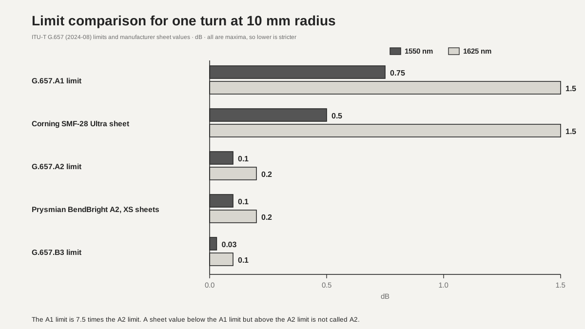 Limit comparison for one turn at 10 mm radius at 1550 nm and 1625 nmView original
-
Allowed loss grows sharply, not linearly, as the radius shrinks
-
A limit divided by turns is a conversion, not a measurement
-
Compare the same wavelength column (1550 or 1625) when you compare radius lines
How do you read sheets that carry the same name but differ?
The documents reviewed differed in three places. First, the Prysmian BendBright A2 North America sheet (December 2025) opens its applicable standards with compliance to both ITU G.657.A1 and G.652.D, and its second item says compliance with IEC 60793-2-50 B-657.A2 and B-652.D. The overview describes the bend performance of a G.657.A2 fiber, and the bend table has the same numbers as the A2 limits above. With A1 and A2 on one page, the sheet alone cannot tell whether one is a typing slip or a note about splice compatibility with A1 fiber. Keep it as an item to confirm with the manufacturer.
Second, sheets under the same BendBright A2 name list a 1310 nm MFD (mode field diameter) of 9.2 ± 0.4 µm in the North American edition and 9.0 ± 0.4 µm in the European edition of November 2023. The XS grade lists 8.8 ± 0.4 µm in both. The Recommendation sets the range of nominal MFD at 8.6 µm to 9.2 µm with a tolerance of 0.4 µm, and Note 4 says macrobending loss is traded off against other attributes such as MFD, chromatic dispersion and cut-off wavelength. These documents alone do not show whether the two sheets describe two editions of one product or two products, so identify a sheet by its document number and issue date, not by its name.
Third, the European XS sheet has 200 in its file name, but its text gives a coating diameter of 160 ± 10 µm. That is an example of why a file name should not identify a document. Also, the 2024 edition of G.657 has no B2, and none of the sheets read printed B2. If an older sheet prints B2, that is a category from an earlier edition, so check that its table rows match the A2 limits. No earlier-edition sheet was read in full for this lesson.
Does a datasheet limit mean the installation passes?
It does not. The Recommendation says macrobending loss in cabled fibre may differ from the uncabled measurement because of the bend-limiting effect of the cable structure, and that studies on the effect of cabling are ongoing. The Prysmian North American sheets head their performance specifications with Uncabled Fiber. The Recommendation also says that installed loss in in-building networks depends on the installation technique, and that demanding techniques such as stapling indoor cable with flat staples are not recommended.
Mechanical risk is separate. The Recommendation says the failure probability under a 30 mm radius bend increases as the radius decreases, and that some installations may need extra constraints such as higher proof test levels. The minimum proof stress in its tables is 0.69 GPa, and the sheets read list 100 kpsi (0.69 GPa) or more for Corning PI1424 and 100 kpsi (0.7 GPa) or more for Prysmian. The Recommendation's appendix on lifetime was not read. In short, a loss inside the limit does not settle the long-term reliability of a small radius.
Cable-level rules use a different unit. A Fiber Optic Association page (copyright 2020) recommends a minimum bend radius of 20 times the cable diameter under pulling tension and 10 times with no tension after installation, while saying products differ and the manufacturer's specification governs. It warns against mixing up radius and diameter and notes that when the rule is a radius of 10 times the cable diameter, a storage loop should have a diameter of at least 20 times the cable diameter. The guide radius printed on a tray or closure drawing comes from the closure and cassette manufacturer's manual, which was not read for this lesson.
What goes into the test record and drawings?
When you record a fiber or cable specification, write the manufacturer and product name, the sheet's document number and issue date, the category name the sheet prints, the whole macrobend line (radius, turns, wavelength, dB), and a note that the radius is a mandrel radius. On a tray or closure drawing, mark whether the guide radius is written as a radius or a diameter, and record the result of checking it against the radius of the sheet line you plan to use. If the sheet's category name and its table values disagree, record the disagreement as it is and note the status of the manufacturer confirmation.
When you compare sheets, match the wavelength column and the turns, and label any proportional conversion as a conversion. The limits of this material are clear. The documents read were one ITU-T Recommendation, six manufacturer sheets and one FOA page. The text of IEC 60793-1-47 and IEC 60793-2-50, the Recommendation's lifetime appendix, and the closure or cassette manuals that give guide radii were not read. Whether a sheet limit comes from testing every fiber or a sample, whether current products still match, and what a real bend-loss measurement would show were not confirmed.
-
Copy all four values of the macrobend line
-
Identify a sheet by document number and issue date, not by name
-
Mark on the drawing whether a guide radius is a radius or a diameter
Checklist
-
Did you find the macrobend line in the datasheet you use and copy its radius, turns, wavelength and dB?
-
Did you check the category the sheet prints (A1, A2, B3) against the table numbers for the same condition in the Recommendation?
-
Did you confirm whether the guide radius of the tray and closure is a radius or a diameter and compare it with the sheet line?
-
Did you record the sheet's document number and issue date, and the manufacturer confirmation status if the category label is inconsistent?
-
Did you keep the cable-level minimum bend radius (a multiple of cable diameter) separate from the fiber mandrel radius?
Review questions
1. Using the G.657.A2 limit, what does a proportional conversion give for three turns at a 10 mm radius at 1550 nm?
Answer and explanation: 0.1 dB × 3 gives 0.3 dB. This is DMS's conversion using the proportional assumption in Note 2 of the Recommendation, not a measured loss.
2. A storage loop in a tray has an inside diameter of 30 mm. Which radius line of the sheet should it be compared with?
Answer and explanation: A 30 mm diameter is a 15 mm radius, so compare it with the 15 mm × 10 turns line (for A2, 0.03 dB at 1550 nm and 0.1 dB at 1625 nm). Mixing up radius and diameter makes a factor of two.
3. The Corning SMF-28 Ultra sheet lists 0.50 dB for one turn at 10 mm at 1550 nm, below the A1 limit. May it be called a G.657.A2 fiber?
Answer and explanation: No. The A2 limit is 0.1 dB for the same condition, and the sheet says only that it exceeds A1. Decide the category from the sentence the sheet prints and from checking the table values against the Recommendation.
Sources
-
ITU-T: Recommendation G.657 (08/2024), Characteristics of a bending-loss insensitive single-mode optical fibre and cable · August 2024 edition, clause 1, 6.6, 6.7.3, Tables 1 and 2 (the PDF download needs a login, so the text on the ITU e-publications page was read)
-
Corning: SMF-28 Ultra product information PI1424 · issued July 2025, supersedes February 2024, 2 pages
-
Corning: ClearCurve ZBL product information PI1464 · issued June 2023, supersedes September 2019, 2 pages
-
Prysmian: BendBright A2 North America TLS-DS-F-004-1225 · issued December 2025, supersedes November 2020, 3 pages
-
Prysmian: BendBright XS North America TLS-DS-F-005-1225 · issued December 2025, supersedes July 2020, 3 pages
-
Prysmian: BendBright A2 Europe datasheet · issued November 2023, 3 pages
-
Prysmian: BendBright XS Europe datasheet (160 µm coating) · issued November 2025, 3 pages
-
FOA: Fiber Optic Cable Bend Radius or Diameter · copyright 2020, cable-diameter multiples and the radius versus diameter distinction