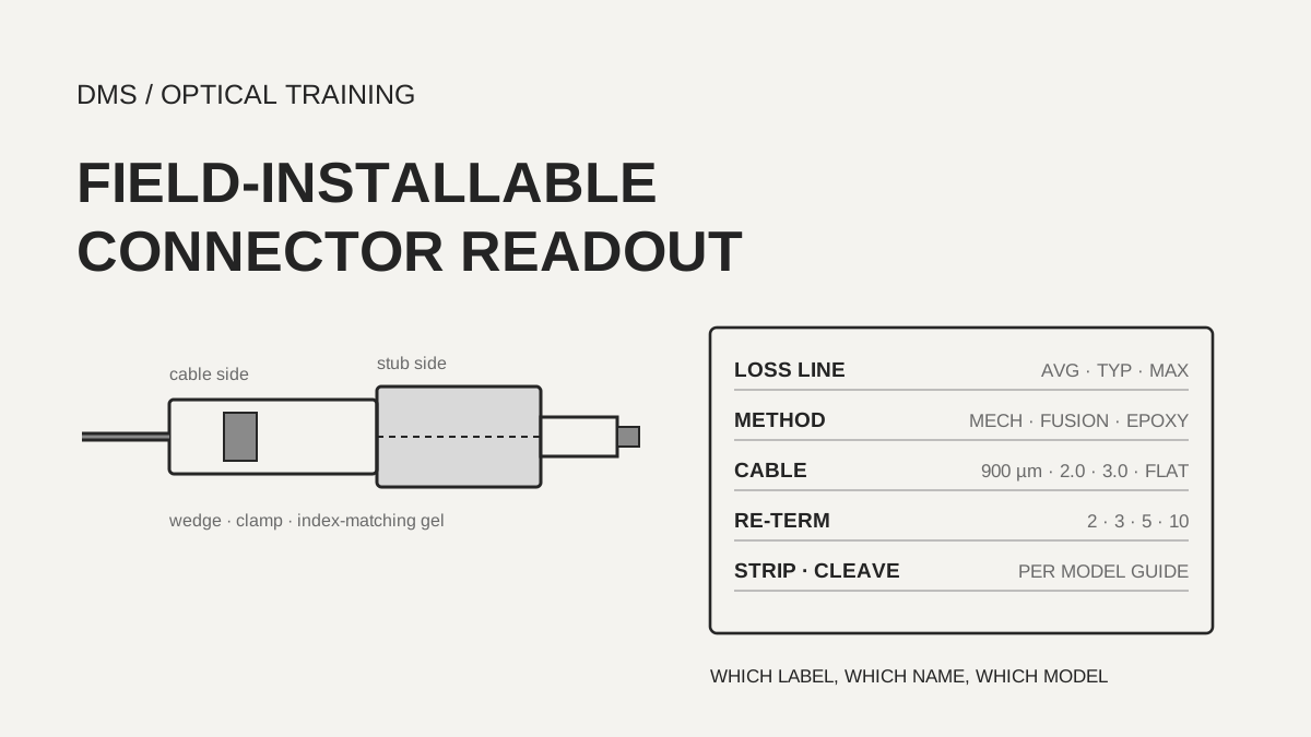
A field-installable connector datasheet prints average, typical or maximum in the insertion loss line, and most of them do not say whether the value includes the loss of the splice point inside the connector. Of the nine manufacturer documents read here, five print an average or typical value together with a maximum (AFL, CommScope, Fibertronics, OMC and SCP), PPC and Teleste print a typical value only, Panduit an average only and Fujikura a limit only. The re-termination count splits as well: the AFL datasheet says three, while the AFL installation guide says five. When copying a value, record the line label (average, typical or maximum), whether a measurement basis is printed, the word used for re-termination and the document code, so that the link loss budget and the work procedure use the same number.
Based on documents checked on November 21, 2026.
Learning objectives
-
Copy each insertion loss line as average, typical, maximum or limit, and note whether a measurement basis is printed.
-
Copy the cable compatibility column with the names printed in the document, and do not merge cables that carry different names.
-
Write the re-termination count and the pull value together with the word and unit, and record a disagreement inside one company's documents as two values.
What basis is the insertion loss line of a field-installable connector datasheet printed on?
The insertion loss line is printed as average, typical, maximum or a limit under the same words, and only one of nine documents, Fujikura, says the value was measured against a reference connector. The AFL datasheet (PP-2-00052 revision 22) and the CommScope Qwik II print average or typical 0.2 dB and maximum 0.5 dB for single-mode UPC, and 0.3 dB and 0.6 dB for APC. Fibertronics, OMC and the SCP ECO series print one pair of values without splitting UPC and APC. PPC and Teleste print a typical value of 0.3 dB or less and no maximum line, and Fujikura prints one limit, 0.5 dB or less for single-mode SPC and 0.6 dB or less for APC. A typical value is not a worst case, so it cannot go into the maximum cell of a link loss budget (DMS interpretation).
What the value contains also differs. Fujikura states in footnote 2 that the value was measured with a reference connector, and the other documents print no basis line. The explainer of the Fiber Optic Association (FOA) says that a pre-polished connector with a mechanical splice carries the connector loss plus the internal splice loss, that the splice adds 0.3 to 0.5 dB, and that 0.5 to 0.7 dB is the best case. That is a general explanation and not a product specification, so which is right against the manufacturers' typical values of 0.2 to 0.3 dB cannot be decided from these documents, and both values are recorded with their sources. The Panduit SC OptiCam document prints an average of 0.3 dB per mated pair in its body text and 0.03 dB in the average insertion loss column of its selection table, so the digits disagree inside one document.
The Fibertronics FieldConx document prints an average of 0.3 dB or less and a maximum of 0.5 dB or less in the connector line on page 1, and an average of 0.2 dB or less and a maximum of 0.5 dB or less in the mechanical splicer line on page 3. Its return loss is printed on page 1 as 50 dB or more for single-mode UPC, and on page 3 as an average of 45 dB or less and a minimum of 40 dB or less, with the inequality pointing the other way. The document does not say what object each line describes, so each is copied as printed with the page it sits on. Teleste prints return loss with a negative sign, UPC at -45 dB or less and APC at -50 dB or less, and AFL prints an average of -50 dB and a maximum of -45 dB. Sign and inequality direction change from document to document, so check first whether a value is read as magnitude or with its sign.
Scroll horizontally to view a wide table.
| Document | Insertion loss line (single-mode) | Line label | Measurement basis printed |
|---|---|---|---|
| AFL FASTConnect datasheet (PP-2-00052 rev 22, 19 September 2024) | UPC 0.2 / 0.5 dB, APC 0.3 / 0.6 dB | average / maximum | none |
| CommScope Qwik II (CO-113709.6-EN) | UPC 0.2 / 0.5 dB, APC 0.3 / 0.6 dB | typical / maximum | none |
| Fibertronics FieldConx | connector 0.3 / 0.5 dB, splicer line 0.2 / 0.5 dB | average / maximum | none |
| OMC Field Fast (22 variant pages) | 0.3 / 0.5 dB | typical / maximum | none |
| SCP ECO series | 0.3 / 0.5 dB | typical / maximum | none |
| Fujikura FAST | SPC 0.5 dB or less, APC 0.6 dB or less | limit only | with a reference connector (footnote 2) |
| PPC field termination connector | 0.3 dB or less | typical only | none |
| Teleste FICS | 0.30 dB or less, 0.50 dB or less after tests | typical / limit after tests | none |
| Panduit SC OptiCam | 0.3 dB (body), 0.03 dB (table) | average | per mated pair (body) |
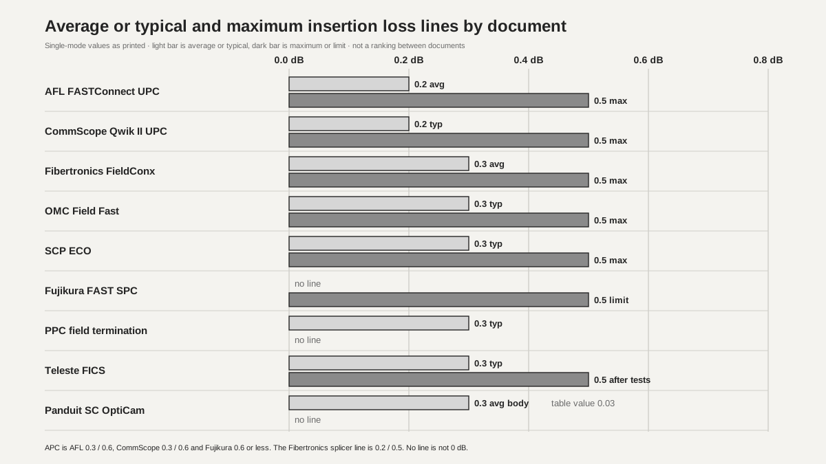 Average or typical and maximum insertion loss lines by documentView original
-
Bars are the single-mode values the documents print. A light bar is average or typical, a dark bar is maximum or limit
-
A cell with no line is written as no line. It is not 0 dB
-
This is not a ranking between documents. The measurement basis differs from document to document
How do mechanical, fusion splice-on and adhesive-polish connectors separate on a datasheet?
Inside the field-installable family, the maximum insertion loss and the tools needed change with the splice method, so the CommScope guide separates three methods into separate families with separate specification blocks. Qwik II is mechanical: a pre-polished stub is butted to the fiber, with a single-mode UPC maximum of 0.5 dB, an APC maximum of 0.6 dB, and up to three re-terminations. Qwik-Fuse is fusion splice-on with a typical 0.15 dB and a maximum of 0.3 dB, and it needs a fusion splicer: the one already in the toolbox with the included ferrule holder, or a purpose-built installer. The adhesive and polish version (anaerobic adhesive) prints a maximum of 0.3 dB and keeps adhesive and polishing tools in separate kits. Return loss follows the same split: Qwik II is 50 dB or more for APC and 45 dB or more for UPC, while Qwik-Fuse and the adhesive version are 65 dB or more for APC and 55 dB or more for UPC.
Among the manufacturer documents read here, the eight other than CommScope all cover one kind only, a factory-polished stub butted to the fiber. Memorizing 0.5 dB from the name field-installable connector would therefore mix in the fusion splice-on rows. The FOA explainer says fusion splice-on connectors perform much better than mechanical ones, but that sentence is also a general explanation and not a product figure (author's explanation). When reading a document, confirm the method in the first line and copy values from the row of that method.
Scroll horizontally to view a wide table.
| CommScope family | Method | Single-mode insertion loss | Single-mode return loss | Re-termination | Tools the document lists |
|---|---|---|---|---|---|
| Qwik II | mechanical, no power | UPC typical 0.2 / max 0.5, APC 0.3 / 0.6 dB | APC 50 dB or more, UPC 45 dB or more | up to 3 | precision cleaver, VFI in the premium kit |
| Qwik-Fuse | fusion splice | typical 0.15 / max 0.3 dB | APC 65 dB or more, UPC 55 dB or more | no line | fusion splicer or purpose-built installer, fiber holders |
| adhesive and polish | adhesive and polishing | max 0.3 dB | APC 65 dB or more, UPC 55 dB or more | no line | adhesive and polishing kits |
In what names and units is the cable compatibility column printed?
Cable compatibility mixes micrometres and millimetres, round and flat, and the same shape carries different names in different documents, so cables that look alike by name must not be merged. Fibertronics splits its list by the last letters of the part number: the U model lists 900 µm, 2.0 mm and 3.0 mm plus drop 2.0*1.6 mm and 2.0*3.0 mm, the R model lists 5.0 mm and 3.0 mm plus the same two drops, and the C model lists the two drops only. OMC prints 0.9, 2.0 and 3.0 mm simplex, 2x3 FTTH drop or 1.6x2.0 drop differently on each of its 22 variant pages. Fujikura lists 0.25 mm fiber (240 to 265 µm), 0.9 mm fiber (850 to 950 µm), 2 mm and 3 mm cord, plus rectangular outdoor cable (3.1 x 2 mm) and indoor cable (2 x 1.6 mm). No document connects the dimension name of the rectangular outdoor cable to the 2.0*3.0 mm drop of Fibertronics.
The CommScope Qwik II lists 250 µm, 900 µm, 3.0 mm and 2.0 mm, but in its material table only models marked UNV take all four, and the others list 0.25 and 0.9 mm. AFL lists 250 µm and 900 µm fiber and 4.8 mm cordage (SC only), and points to separate boot kits for 2 mm and 3 mm. Panduit lists 900 µm buffered fiber or 250 µm fiber with a 900 µm build-up, and 1.6 to 2.0 mm and 3.0 mm jacketed cable with optional boots. PPC prints all types of fiber and cable diameter in its feature line, only 900 µm, 2.0 mm, 3.0 mm and 2 x 3 mm flat cable in its specification line, and an ordering table that selects 0.250, 0.9, 2.0, 3.0 mm, flat cable or a universal U. The ordering table also selects the fiber type, which has to be read separately: PPC splits G.652D, G.657A1 (bend 10 mm), G.657A2 (7.5 mm), G.657B3 (5 mm) and G.655 by code, and Fibertronics prints G.657A1, A2 and B3 in its splicer line. The documents do not say what happens to loss when the stub fiber type differs from the cable fiber.
Scroll horizontally to view a wide table.
| Document | Words in the cable column | Split inside the column |
|---|---|---|
| Fibertronics FieldConx | 900 µm, 2.0 mm, 3.0 mm, 5.0 mm, drop 2.0*1.6, drop 2.0*3.0 | part number ending -U, -R, -C |
| OMC Field Fast | 0.9/2.0/3.0 mm simplex, 2x3 and 1.6x2.0 FTTH drop | 22 variant pages |
| Fujikura FAST | 0.25 and 0.9 mm fiber, 2 and 3 mm cord, rectangular outdoor 3.1 x 2 mm, indoor 2 x 1.6 mm | LC is indoor only (footnote 5) |
| CommScope Qwik II | 250 µm, 900 µm, 3.0 mm, 2.0 mm | only UNV models take all four |
| AFL FASTConnect | 250 and 900 µm fiber, 4.8 mm (SC only), 2 and 3 mm by boot kit | by part number |
| Panduit SC OptiCam | 900 µm, 250 µm with 900 µm build-up, 1.6 to 2.0 mm, 3.0 mm | boots are optional |
| PPC | all types in the feature line, 900 µm, 2.0, 3.0 mm and 2 x 3 mm flat in the specification line | digit 7 of the order code |
| SCP ECO | 250 µm, 900 µm, 2.0 mm, 3.0 mm | one kind per part |
Do the re-termination count and the pull value mean the same thing in every document?
The re-termination count is printed with different words, reinsert, re-terminate, repeat assembly and reusable, and one company's datasheet and installation guide give different numbers, so copying the number alone loses the condition. The AFL datasheet says the fiber can be reinserted up to three times, and the installation guide dated 5 January 2026 (INS-01056) says the connector can be re-terminated up to five times by putting the wedge clip back on. The guide also states that if the fiber breaks inside the connector body, the connector cannot be re-terminated. CommScope says Qwik II can be re-terminated up to three times and Panduit says up to two times with no degradation. SCP prints a recommended maximum of five re-terminations, Fibertronics repeat assembly of 10 or more, and Teleste reusable times of 10. PPC says only that the connector is re-usable and gives no count, and OMC and Fujikura have no count line.
Pull values differ in object and unit as well. Fibertronics prints 30 N or more (5 N or more for 0.9 mm round cable) and gives the splicer line a time: 2 N for 30 seconds on 250 µm fiber and 4 N for 30 seconds on 900 µm fiber. OMC prints 30 N or more and only two variant pages (15 and 24) print 50 N or more. Teleste prints tensile 5 N, coating tightening 10 N and a separate line of insertion loss 0.50 dB or less after an on-line tensile test at 20 N. SCP prints an average sustained tension of 6.5 lb for 2.0 and 3.0 mm cable and 2.0 lb for 250 and 900 µm fiber, which at about 4.448 N per lb is about 28.9 N and about 8.9 N (DMS conversion). Panduit prints the cable retention test loads in lb and kg. Where a document says only tensile, with no test time, no loss change limit and no statement of average or minimum, record that gap as it is.
Scroll horizontally to view a wide table.
| Document | Words in the re-termination line | Count | Pull or retention line |
|---|---|---|---|
| Panduit SC OptiCam | up to two re-terminations | 2 | cable retention test load 11.24 lb (5.09 kg) printed |
| CommScope Qwik II | re-terminated up to three times | 3 | no line |
| AFL datasheet (rev 22) | reinserted up to three times | 3 | no line |
| AFL installation guide (INS-01056) | re-terminated up to 5 times | 5, not possible if the fiber breaks in the body | no line |
| SCP ECO | recommended maximum re-termination | 5 | 6.5 lb (about 28.9 N) and 2.0 lb (about 8.9 N), average |
| Fibertronics FieldConx | Repeat Assembly | 10 or more | 30 N or more, 0.9 mm round 5 N or more, splicer 2 N and 4 N for 30 s |
| Teleste FICS | Reusable Times | 10 | 5 N, coating tightening 10 N, 0.50 dB or less after 20 N |
| OMC Field Fast | no line | none | 30 N or more, two variants 50 N or more |
| PPC | Re-usable | no count | no line |
| Fujikura FAST | no line | none | no line |
Where are the strip and cleave lengths and the assembly checks copied from?
Strip and cleave lengths differ by model, so they are copied from the installation guide of that model and not from the datasheet, and an assembly check shows contact, not an insertion loss value. The AFL guide says to strip 35 mm of coating on 250 µm fiber and 35 mm of 900 µm and 250 µm coating on 900 µm fiber, with a recommended cleave length of 10.5 mm and a minimum of 10 mm for both. The SCP guide strips 10 mm of cable jacket and 10 mm of buffer, cleaves 10 mm from the mark and strips a further 20 mm of jacket. Teleste says to fit the cutting jig against the cleaver stopper and prints 22.5 mm and 7 to 8 mm on a drawing, but the drawing is marked as a reference, so the object of those lengths is not fixed here. That two documents print different lengths is reason enough not to carry the numbers of one model to another.
The checks differ too. The AFL datasheet says a translucent wedge and a visual fault identifier (VFI) give a pass or fail signal once physical contact is made, and the ST procedure in the guide says the light in the wedge window dims when contact is made and warns that once the ST housing is on the wedge cannot be released again, so check before fitting it. CommScope puts a VFI and a high-precision cleaver in its premium kit, Panduit says the OptiCam 2 tool shows a calculated insertion loss at termination, and SCP prints a large verification window. FOA explains that a good cleaver, a VFL, training and practice decide the termination yield (author's explanation). All of these are manufacturer or association statements, not independent tests. Loss after termination has to be confirmed by a separate OLTS or OTDR measurement.
Scroll horizontally to view a wide table.
| Document | Strip and cleave | Check the document prints |
|---|---|---|
| AFL installation guide | 35 mm coating strip, cleave length 10.5 mm recommended (10 mm minimum) | VFI and the red light in the wedge window (ST procedure in the guide), check before the housing |
| SCP ECO | 10 mm jacket, 10 mm buffer, cleave 10 mm from the mark, a further 20 mm jacket | verification window, amber button |
| Teleste FICS | jig against the cleaver stopper, drawing 22.5 mm and 7 to 8 mm | no line |
| CommScope Qwik II | no line | VFI and high-precision cleaver in the premium kit |
| Panduit SC OptiCam | no line | OptiCam 2 calculated insertion loss, translucent inner housing |
| FOA explainer | general description | good cleaver, VFL, training and practice |
What happens when site conditions are put against the datasheets?
The cases here are hypothetical teaching calculations, and no real site or product was tested. The first case is field termination of SC/APC on 2.0 x 3.0 mm flat drop cable. Fibertronics and OMC print a flat 2.0*3.0 mm name and APC, and PPC prints both flat 2 x 3 mm cable and an APC order code, so they match. Teleste prints a 2 * 3.0 mm drop on a drawing and can be counted as a match, but its specification table has no cable column. Fujikura prints a rectangular outdoor cable of 3.1 x 2 mm under a different name, so it cannot be judged. CommScope, Panduit, AFL and SCP do not print flat cable, which is written as no line and not as incompatible.
The second case puts the APC maximum per connector into a link loss budget. AFL, CommScope Qwik II and Fujikura print 0.6 dB for APC, and Fibertronics, OMC and SCP print 0.5 dB without splitting UPC and APC. PPC and Teleste have no maximum line and cannot fill the worst-case cell. The third case needs three re-terminations in the plan. Panduit says two and does not match, CommScope and AFL say three and match, and AFL's guide says five so the two values are written together. SCP at 5, and Fibertronics and Teleste at 10, match, while PPC, OMC and Fujikura have no count line and cannot be judged.
The limits of this material are clear. The texts of IEC 61754-20, IEC 61753-1, the TIA-604 series (FOCIS), TIA-568.3-D, and Telcordia GR-326 and GR-1081 were not read. Whether the AFL, CommScope and other documents are the current revision, or match the models on sale today, was not confirmed. Some tables of the Fibertronics, SCP and PPC documents were read by text extraction, and which model each column belongs to was not confirmed from page images for all of them. Every value is published by the manufacturer and is not an independent test.
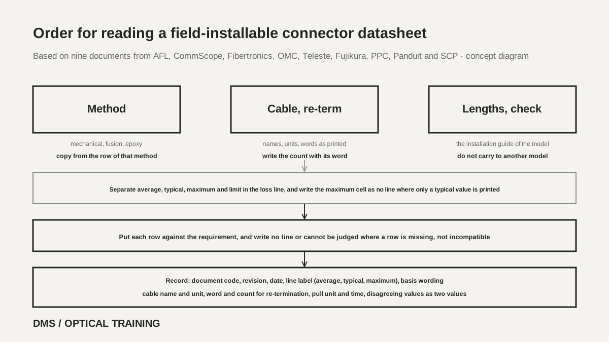 Order for reading a field-installable connector datasheetView original
-
Separate the method first and copy insertion loss from the row of that method
-
Copy the cable column and the re-termination count with the names and words as printed
-
Copy strip and cleave lengths from the installation guide of the model, and write no line where there is none
Scroll horizontally to view a wide table.
| Hypothetical condition | Line present | Label or disagreement | Cannot be judged or no line |
|---|---|---|---|
| Flat 2.0 x 3.0 mm drop, SC/APC | Fibertronics, OMC, PPC | Teleste only on a drawing | Fujikura different name, others no line |
| APC maximum insertion loss | AFL 0.6, CommScope 0.6, Fujikura 0.6 | Fibertronics, OMC, SCP one pair at 0.5 | PPC, Teleste no maximum line |
| Three or more re-terminations | CommScope 3, AFL 3, SCP 5, Fibertronics 10, Teleste 10 | AFL guide says 5 | Panduit 2 does not match, PPC, OMC, Fujikura no count line |
Checklist
-
Did you write whether the insertion loss line is average, typical, maximum or a limit, and whether a measurement basis is printed?
-
Did you confirm the method (mechanical, fusion splice-on, adhesive and polish) first and copy the value from the row of that method?
-
Did you copy the cable as named and with the unit in the document, without merging flat cables that carry different names?
-
Did you write the re-termination count with its word and the document code, and the pull value with its unit and test time?
-
Did you copy strip and cleave lengths from the installation guide of the model, and write that loss after termination is confirmed by a separate measurement?
Review questions
1. A datasheet has one line for SC/APC, typical 0.3 dB or less, and no maximum line. May it go into the worst-case cell of a link loss budget?
Answer and explanation: It may not. A typical value is not a worst case, so write the maximum cell as no line and, if a maximum is needed, confirm it from another document or test report for the same model. If a value is used provisionally in the budget, mark it as an assumption together with its source (DMS interpretation).
2. The AFL datasheet says the fiber can be reinserted up to three times, and the installation guide says it can be re-terminated up to five times. Which value goes into the work standard?
Answer and explanation: Do not pick one side. Write both values with the document codes and dates. Whether the two differ because of a revision cannot be known from the documents, so use the lower value in the plan, record the reason, and check the current installation guide of the model. Copy the condition as well: if the fiber breaks inside the connector body, it cannot be re-terminated.
3. The body of the Panduit SC OptiCam document says an average of 0.3 dB per mated pair, and its selection table says an average insertion loss of 0.03 dB. How is it copied?
Answer and explanation: Write both values with their page positions and record that which one is right cannot be known from this document. Do not pick one or average them, and if the value goes into a budget, confirm it with the manufacturer's current datasheet or a test report.
Sources
-
AFL: FASTConnect Field-Installable Connectors datasheet (PP-2-00052 revision 22, 19 September 2024) · pages 1 to 2
-
AFL: FASTConnect Connector Termination and Assembly Instructions (INS-01056, 5 January 2026) · pages 1 to 3
-
CommScope: Field Installable Fiber Optic Connector Guide (CO-113709.6-EN, 11/24) · pages 2 to 10
-
Fibertronics: FieldConx Series Datasheets (no printed date) · pages 1 to 4
-
OMC: Field Fast Installation Fiber Optic Connector datasheet (2018, En version 1.0) · pages 1 to 24
-
Teleste: Fibre FICS Connector datasheet (TEN-FICS_211124) · pages 1 to 4
-
Fujikura: FAST Connector Series (JSAA-13-24-0021A 2406-2603) · pages 1 to 3
-
PPC: Field Termination Connector Spec Sheet (rev3_10122022) · pages 1 to 2
-
Panduit: SC OptiCam Pre-Polished Fiber Optic Connectors (FBSP17-WW-ENG, 7/2024) · pages 1 to 2
-
SCP: ECO Series Field-Assembly SC Type Fiber Optic Connectors technical specifications (no printed date) · pages 1 to 2
-
FOA: Splice-On Connectors With Mechanical Splices And Fusion Splices (2025)