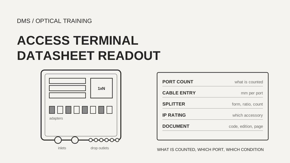
An FTTH terminal datasheet does not give capacity as one port count. Adapters, splices, drop outlets and splitter outputs are counted differently from document to document, so the first check is the name of the row. In the nine manufacturer documents and one requirements document read here, one product is printed with 8 adapters and 96 splices, a product named 48F has 12 adapters and 72 splices, and the IP rating runs from IP55 to IP68. When copying a value, write down what is being counted, the diameter range of each cable inlet and outlet, the type of grommet (the rubber seal that grips a cable) or cable gland, the form and ratio of the splitter, and the accessory condition behind an IP rating, so that the figure can be checked against site conditions.
Based on the documents checked on 18 November 2026.
Learning objectives
-
Tell whether a capacity figure counts adapters, splices, drop outlets or splitter outputs from the name of its row, and copy each one separately.
-
Read cable inlet and drop outlet diameters as a range per port together with the grommet type, and match them against the cable cross-section on site.
-
Write IP and impact ratings together with the accessory and the sample state, and record any figure that disagrees within a document as two values.
What does the port count on a terminal datasheet actually count?
A capacity figure counts one of adapters, splices, drop outlets or splitter outputs, and a single document often prints figures for different things side by side. The FCST02259-F document gives a maximum capacity of 8 cores (SC/APC) and a closure (FOSC) capacity of 96 cores on the same product line. There are 4 trays of 24 cores each, which makes 96, and 8 pre-connected adapters (DMS calculation). The Teleste TEN-FWB9 is named 48F and lists 48 outlet ports, but its adapters are 12 SC or 24 LC, and 6 trays with 12 splice holders each make 72 splice positions (DMS calculation). Reading the number in a product name as the number of subscribers served would assign 48 homes to a box with 12 adapters.
The Technetix FTB Connect lists 13 SC adapters (16 optional) or 26 LC, 72 splices and 6 trays, and its cable access ports are 2 on top, 2 on each side and 4 on the bottom, 10 in all. The STL FOTB 16 lists 24 SC adapters, 48 splice holders and 2 LGX splitters in one table, and the FOTB 8 lists 12 adapters and 24 holders. The only row that matches the 8 in the model name is the maximum drop port count for 5 to 8 mm round cable, so reading the name as the adapter count would turn 12 into 8. FCST022109-17 has 17 Ports in its name but 1 inlet and 16 outlets and a maximum capacity of 16 cores, and the document does not define the 17.
The Technetix LB-TB-MDU document prints 8 or 16 SC adapters and a 1x16 splitter in the same table as a maximum capacity of 12 cores. The PPC 16F terminal describes 16 drops and 16 outlet ports and lets the order code choose 6, 8, 12 or 16 adapters. The Clearfield YOURx MPT specification table lists eight 14 mm distribution ports, while the port-count choice in its ordering section goes up to 16 ports, and its splice chip holds 12 loose-tube splices or 3 mass-fusion splices (36 fibers). When the specification table and the ordering table of one document give different numbers and the document does not say which configuration each belongs to, write both separately.
The TEC (Telecommunication Engineering Centre, India) requirements document defines five box types and fixes adapter and splice counts for each. The outdoor MDU box (Type III) takes one 24-fiber cable and has 24 adapters and 24 splices, and the outdoor FDH (Type V) has 108 adapters and 108 splices. Putting a manufacturer's figures beside the matching TEC type gives a sense of the scale of the box, but the two documents differ in author and purpose, so they are not used to pass or fail each other.
Scroll horizontally to view a wide table.
| Document | Number in the name | Adapters and ports | Splices | Inlets and outlets | Note |
|---|---|---|---|---|---|
| Technetix LB-TB-MDU-8 / -16 | 8 / 16 | SC 8 / 16 | No row (maximum capacity 12 cores) | 2 inlets, 8 / 16 outlets | Capacity row of 12 and 16 ports in the same table |
| Technetix FTB Connect | None | SC 13 (16 optional) or LC 26 | 72 (6 trays × 12) | 10 access ports | Splitters: 4 in the base or 2 per tray |
| STL FOTB 8 / 16 | 8 / 16 | SC 12 / 24 | Holders 24 / 48 | 1 mid-span entry, 1 distribution entry | Maximum drops 12, 12, 8 / 24, 24, 16 |
| Teleste TEN-FWB9 | 48F | SC 12 or LC 24 | 72 (6 trays × 12, DMS calculation) | 2 inlets, 48 outlets | Order codes go up to 24 LC duplex adapters |
| FCST02259-F | None | 8 pre-connected adapters (or 9) | 96 (4 trays × 24 cores, DMS calculation) | Inlets and outlets 2 / 8 | Tray types hold 6 to 24 cores |
| FCST022109-17 | 17 Ports | Pre-connected | No row | Inlets and outlets 1 / 16 | Maximum capacity 16 cores |
| PPC 16F | 16F | 6, 8, 12, 16 (order code) | No row | 2 inlets, 16 outlets | No IP, temperature or diameter rows |
| Clearfield YOURx MPT | None | 8 ports of 14 mm (specification table), 16 (order code) | 12 loose-tube or 36 mass-fusion fibers | 1 feeder | No explanation linking the two numbers |
| TEC requirement (Type III outdoor MDU) | None | 24 | 24 cores | 5 cable entries | Requirements document, not a product |
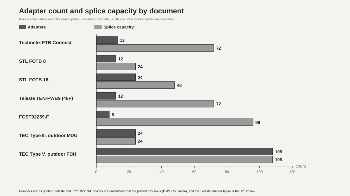 Adapter count and splice capacity by documentView original
-
The bars show the adapter count and the splice capacity each document prints
-
Constructions differ, so this is not a ranking under one condition
-
The TEC rows are values from a requirements document, not a product
What diameters are printed for cable inlets and drop outlets?
Inlet and outlet diameters are ranges per port type, and in many documents the grommet has to be changed to fit the range. The Technetix LB-TB-MDU has 2 inlets of up to 12.0 mm and 8 or 16 outlets of up to 5.0 mm each. The FTB Connect takes cables of 3 mm to 12 mm through grommets, and the supplied set is one 10 mm, two 7 mm, one 2×7 mm, two 12×5 mm and two 24×3 mm. The same box accepts different cables depending on which grommet goes into which port. The STL FOTB has a mid-span entry of 6 to 15 mm and a distribution cable entry of 3 to 15 mm, and the number of drop ports falls with the cable: on the FOTB 16 it is 24 for 2×3 mm flat or 3 mm round cable and 16 for 5 to 8 mm round cable. A footnote says the accessories vary with the cable diameter.
The Teleste TEN-FWB9 lists a maximum input cable of 10 mm and a maximum output cable of 2.9 mm, and the FCST02259-F prints a port diameter of 8 to 14 mm. The Clearfield MPT accepts a feeder cable of up to 0.70 in (17.78 mm) and tells the installer, in several places in the specification and ordering pages, to choose between the grommet for 0.45 to 0.70 in round cable and the one for 0.44 in or less. Its distribution ports are 14 mm and are designed for the FlexConnector. A flat drop cable has two cross-section dimensions, so one diameter row cannot judge it. Only documents that print the flat cross-section directly can be used for flat cable, as STL does with 2×3 mm flat against 3 mm round, and FCST022109-17 does with its optional 2.0×5.0 mm pre-connectorized drop.
For pre-connected terminals the entry problem turns into a connector compatibility problem. FCST022109-17 offers SC (XL), Huawei mini SC and Corning OptiTap adapters, and FCST02259-F uses the Huawei hardened adapter and says it is used together with FastConnect distribution cable. A port may fit physically and still not mate if the connector family on the drop cable differs, so record the connector family separately from the diameter row. The Technetix feed and drop cable material says the pulling eye is designed for a maximum pulling tension of 100 lb, about 445 N (DMS calculation). It does not say whether this is short term or long term, or under what test. It also says the pushable fiber is designed to pass through a 3/8 in (9.52 mm) opening.
The numbers in a requirements document are written differently from a manufacturer's table. Table 1 of the TEC document gives the cable diameter of the cable entry ports as 6 to 14 mm and 5 entry ports for Type III, while clause 2.1 requires a sealing arrangement for cables of 4 mm to 14 mm. The lower limit is 4 mm in one place and 6 mm in another inside the same document, and the document alone does not show which is right. The PPC 16F prints 2 inlets and 16 outlets but no diameter, so a diameter judgement is recorded as not possible.
Scroll horizontally to view a wide table.
| Document | Inlet (feeder) | Outlet (drop) | Clamping and sealing parts | Note |
|---|---|---|---|---|
| Technetix LB-TB-MDU | 2, up to 12.0 mm | 8 or 16, up to 5.0 mm each | Rubber gasket, feeder and drop clamps | No flat cross-section defined |
| Technetix FTB Connect | 10 access ports, 3–12 mm | No split between inlet and outlet | Grommet set, 2 clamps for aramid | IP64 needs the optional cable glands |
| STL FOTB | 1 mid-span entry, 6–15 mm | 1 distribution entry 3–15 mm, interchangeable drop ports | Cable anchoring, rain cap | Number of drops depends on cable type |
| Teleste TEN-FWB9 | 2, up to 10 mm | 48, up to 2.9 mm | Lockable lid | Smallest outlet limit |
| FCST02259-F | Port diameter 8–14 mm | 8 pre-connected adapters (or 9) | 1 oval entry or 1 round entry | Description of the inlets differs |
| FCST022109-17 | 1 | 16 | 5 mm or 2.0×5.0 mm pre-connectorized cable | 3 connector families |
| Clearfield YOURx MPT | Up to 17.78 mm | 8 ports of 14 mm | 2 split grommets | Warning to select the right grommet |
| TEC requirement (Type III) | 5 entries, 6–14 mm | Patch cord outlet | Rubber grommets | Clause 2.1 says 4–14 mm |
| PPC 16F | 2 inlets | 16 outlets | No row | No diameter row |
Where and how many splitters fit, and in what form?
Splitter capacity is printed not as a single line saying 1x16 is possible but as a combination of mounting position, form, count and a list of ratios. The Technetix LB-TB-MDU lets the buyer order a factory-installed 1x8 or 1x16 PLC splitter with order codes 108 and 116, and tells the reader to ask the factory about other PLCs. The FTB Connect says only 4 PLCs in the base or 2 per tray and does not give a ratio. The STL FOTB takes 1 LGX (1:8) splitter on the FOTB 8 and 2 on the FOTB 16, and its tube-type PLC holder is one 1:8 on the FOTB 8 and three of 1:8, 1:16 or 1:32 on the FOTB 16. Page 5 of the document says the installer can choose between an adapter-holder design and a splitter design to suit the conditions, which reads as a swap between the 12 or 24 adapters and the LGX position (DMS interpretation). The document does not say whether adapters and splitters can both be filled to their maximum at once.
The Teleste lists only 2 splitters of 1x4 or 1x8 per tray, 4×7 mm in size, and no 1x16. The FCST02259-F puts 1x2, 1x4, 1x8 (60×7×4 mm) or 1x16 (60×12×4 mm) in a splitter tray, one per tray and at most 4, and the splice capacity of a splitter tray differs by type at 6, 24 or 18 cores. Splitters can take up positions that splice trays would use, so the 96-core capacity is not read as usable together with splitters. The configuration rule 1A=2B=2C=1D=1E appears to be a conversion where one tray of a type takes the place of two of another type, and the document does not explain it (DMS interpretation). The Clearfield MPT lists part numbers for 1x2, 1x4 and 1x8 splitters, its ordering code has a 1x6 choice, and there is no 1x16. A 1x6 is an unusual split ratio, and whether it is a misprint was not confirmed.
Scroll horizontally to view a wide table.
| Document | Splitter form and position | Ratios and count | Note |
|---|---|---|---|
| Technetix LB-TB-MDU | Factory-installed PLC (codes 108 / 116) | 1x8, 1x16 | Ask the factory about other PLCs |
| Technetix FTB Connect | 4 in the base or 2 per tray | No ratio row | Count only |
| STL FOTB 8 | 1 LGX, 1 tube-type holder | 1:8 | Swap choice with the adapter-holder design |
| STL FOTB 16 | 2 LGX, 3 tube-type holders | 1:8, 1:16, 1:32 | Swap choice with the adapter-holder design |
| Teleste TEN-FWB9 | 2 per tray, 4×7 mm | 1x4 / 1x8 | No 1x16 row |
| FCST02259-F | Splitter tray, 1 per tray | 1x2, 1x4, 1x8 (60×7×4 mm), 1x16 (60×12×4 mm), up to 4 | Trays hold 6, 24 or 18 cores |
| FCST022109-17 | Built in | 1x16 | Configuration where the box is not opened |
| PPC 16F | 1 or 2 PLCs chosen in the order code | 1x8, 1x16 | Modular option available |
| Clearfield YOURx MPT | Bulkhead mount, by part number | 1x2, 1x4, 1x8 (1x6 also in the order code) | No 1x16 row |
How are ingress protection and test conditions printed?
IP and impact ratings are printed as bare figures, and most datasheets do not say in what state the product was tested. The Technetix LB-TB-MDU is IP55 for the -8 and IP65 for the -16 in the same family, so the whole family cannot be read as IP65. The FTB Connect is IP55 and is printed as IP64 with the optional cable glands, so the rating of one box changes with the accessory. For impact, Teleste prints IK08 under EN 62262 and the FTB Connect prints IK-08, while the Technetix LB-TB-MDU prints an impact resistance of 200 kg-cm/cm² or more at room temperature without an IK rating or a test object. It also prints a tensile strength of 2,000 N/m² or more. N/m² is a unit of pressure and cannot be compared with a cable holding force, and it looks like a material property, which the document does not explain (DMS interpretation).
STL prints IP65 and says the box is designed to work in the environmental categories C (controlled), G (outdoor ground level) and A (aerial) defined in IEC 61753-1. Both FCST documents and the Technetix FST and MST series print IP68, and the Clearfield MPT says it is designed, tested and certified to Telcordia GR-771 and IP68. The PPC 16F has only the description of high-impact plastic and no IP rating, impact figure or temperature row. The immersion conditions (depth and duration) behind IP68 are not printed in any document read here, so the number alone does not say what immersion the box withstands.
The conditions in a requirements document are also worth reading. The TEC general requirements for FTTH boxes (second issue, April 2010) require IP65 for the outdoor MDU box and the outdoor FDH and IP55 for the indoor and semi-covered types, and say the IP rating is to be tested on a fully loaded box. One sample is built with the smallest cable and one with the largest, with all adapters and pigtails fitted. An axial tension of 70 N is applied to the cable for 10 minutes (attenuation change within ±0.10 dB) and 25 N to pigtails and patch cords for 10 minutes. The shower test uses 4 nozzles at 40 L/min each, a distance of 400±100 mm and 1 hour, with no water ingress allowed. The temperature cycle is minus 15 to plus 60 degrees Celsius for 10 cycles. The minimum fiber bend radius is 35 mm and the minimum coil diameter in the tray is 70 mm, which is a different criterion from the bend radius control of more than 40 mm that Technetix prints. No document says whether a manufacturer's IP65 came from conditions like the full-load and shower tests of TEC.
Scroll horizontally to view a wide table.
| Document | IP | Impact | Temperature | Condition wording |
|---|---|---|---|---|
| Technetix LB-TB-MDU-8 | IP55 | 200 kg-cm/cm² or more (room temperature, object not stated) | −40 to +85 °C | The -16 in the same family is IP65 |
| Technetix LB-TB-MDU-16 | IP65 | Same | −40 to +85 °C | No row for the sample state |
| Technetix FTB Connect | IP55 / IP64 (optional cable glands) | IK-08 | No row | The rating changes with the accessory |
| STL FOTB | IP65 | No row | No row | IEC 61753-1 categories C, G, A; UV 1,000 hours |
| Teleste TEN-FWB9 | IP65 | IK08 (EN 62262) | −40 to +85 °C | UV and flame ratings given separately |
| FCST02259-F | IP68 | No row | No row | No row for immersion conditions |
| FCST022109-17 | IP68 | No row | Storage −40 to +65 °C | No operating temperature row |
| Technetix FST and MST | IP68 | No row | −40 to +85 °C | No row for immersion conditions |
| Clearfield YOURx MPT | IP68, GR-771 | No row | No row | Designed, tested and certified wording |
| PPC 16F | No row | High-impact plastic wording only | No row | No figures |
| TEC requirement | Types II and IV IP55, Types III and V IP65 | High impact resistance without a figure | Cycle −15 to +60 °C | Fully loaded sample, shower test |
How do you record figures that disagree inside one document?
Some documents contradict themselves in figures or wording, and the right way is not to choose a side but to write both values with the document code. The Technetix LB-TB-MDU prints a maximum capacity of 12 cores together with 16 ports, 16 SC adapters and a 1x16 splitter in the same table, so what the 12 counts is unknown. Teleste prints a maximum of 12 SC or 24 LC adapters, while its order codes include 24 LC/APC duplex adapters with 48 pigtails. If the 24 LC in the table is a count of adapters, it matches the order code, and if it is a count of connectors it makes 12 adapters and does not, so the missing unit is the problem. The FCST02259-F prints inlets and outlets as 2 and 8, while its feature list says one oval inlet with 8 adapters, or one round inlet with 9 adapters.
In some documents the page count in the header differs from the page count of the file. The FCST02259-F header reads page 1 of 7 but the downloaded file has 5 pages, and the FCST022109-17 header reads page 1 of 6 but the file has 4. Whether pages are missing was not confirmed. The weight row of FCST022109-17 is 900 g and the packing row is 1 kg per piece, and it is not stated whether packing is included. That document says pre-connected design raises installation efficiency by 80% or more, and the Technetix brochure says installation time is reduced by up to 50%. Neither gives a basis for comparison or test conditions, so they are manufacturer claims and are not used as evidence in this lesson.
Dates and editions are recorded, not judged. The Technetix LB-TB-MDU is 11/2023 EN/V1, the FTB Connect 06/2024 EN/V7 and the access terminal brochure 10.2024-V3. The Teleste file code carries 221122 and the copyright is 2022, and the date format is not explained. The Clearfield MPT is V05.26, the PPC 16F is rev3_06132022 and the TEC document is the second issue of April 2010. The STL and the two FCST documents carry no printed date or edition. No manufacturer was contacted about the disagreeing figures, and both values are written as printed.
Scroll horizontally to view a wide table.
| Where it disagrees | One side | Other side | How to record |
|---|---|---|---|
| Technetix LB-TB-MDU capacity | Maximum capacity 12 cores | 16 ports, 16 SC adapters | Write both rows as printed and mark the definition of 12 as to be confirmed |
| Technetix LB-TB-MDU tensile strength | 2,000 N/m² or more | No cable holding force row | Note the pressure unit and do not use it for cable anchoring |
| Teleste adapter count | 12 SC or 24 LC | Order code 24 LC duplex, 48 pigtails | Mark the unit as not stated |
| FCST02259-F inlets and adapters | Inlets and outlets 2 / 8 | 1 inlet with 8 or 9 adapters | Write both descriptions |
| FCST022109-17 port count | Name 17 Ports | Inlets and outlets 1 / 16, maximum 16 cores | Mark the definition of 17 as to be confirmed |
| Page counts of the two FCST documents | Header 1/7 and 1/6 | File of 5 and 4 pages | Record possible missing pages as unconfirmed |
| Clearfield MPT port count | 8 ports of 14 mm in the specification | Order code up to 16 ports | Write both values and mark the configuration to be confirmed |
| TEC cable diameter lower limit | Clause 2.1 says 4 mm | Table 1 says 6 mm | Write both values |
What happens when site conditions are put against the datasheet values?
The cases here are hypothetical teaching calculations and not tests of a real site or product. The first is an outdoor wall-mounted box for 16 homes with one 10 mm feeder cable, sixteen 2.0×5.0 mm flat drops, a 1x16 splitter inside and a requirement of IP65 or higher. The Technetix LB-TB-MDU-16 matches on inlet, 1x16 and IP65, but its outlet limit of 5.0 mm is a diameter figure, so a flat cross-section cannot be judged, and the 12-core capacity row remains. The STL FOTB 16 matches on inlet, 1:16 and IP65, and flat cable is printed only as 2×3 mm, so 2.0×5.0 mm has no row, while 5 to 8 mm round cable would give 16. The Teleste exceeds its 2.9 mm output limit and has no 1x16 row. FCST022109-17 prints the 2.0×5.0 mm pre-connectorized cable, 1x16 and IP68, but the connector family (SC XL, mini SC, OptiTap) has to be matched to the drop cable. The PPC 16F has no diameter or IP row and cannot be judged, and the Clearfield MPT falls short with 8 ports in its specification table, so the 16-port configuration in the order code has to be confirmed, and it has no 1x16 row.
The second case requires the same box to stand up to a rainy day with all 16 drops connected. No manufacturer document says whether its IP65 is a value for the fully loaded state, and TEC requires testing on a fully loaded sample. So the IP rating is not written as the number beside the box name, but after the gland or grommet configuration and the sample state have been checked. The third case is pulling pre-connected drop cable through a duct. If the expected pull is assumed to be 600 N, it exceeds the Technetix pulling eye of 100 lb (about 445 N) by about 155 N. The document does not say short or long term, so whether it can be used as a limit for the pull is not settled, and the pulling method follows the manufacturer's procedure.
The limits of these sources are clear. The texts of IEC 60529 (IP code), IEC 62262 and EN 62262 (IK code), IEC 61753-1, Telcordia GR-771, GR-326 and GR-1435, and UL 94 were not read, and how each rating is defined by test was not confirmed. The TEC document is a procurement requirement of an Indian operator and is neither an international standard nor a Korean one. Whether each document is the current revision and matches the product on sale today was not confirmed. All figures are values published by the manufacturers and are not independent tests.
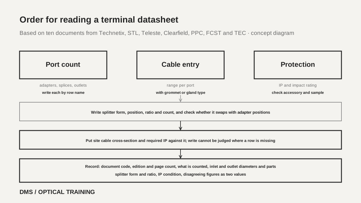 Order for reading a terminal datasheetView original
-
Separate adapters, splices, drop outlets and splitter outputs by the name of the row
-
Copy inlets and outlets as a range per port with the grommet or gland type
-
Check the accessory and sample state behind a rating, and write that a row is missing when it is
Scroll horizontally to view a wide table.
| Hypothetical condition | Inlet 10 mm | 16 drops of 2.0×5.0 mm | 1x16 splitter | IP65 or higher |
|---|---|---|---|---|
| Technetix LB-TB-MDU-16 | Within 12.0 mm | Outlet up to 5.0 mm, flat cross-section undefined, cannot be judged | Orderable (code 116) | IP65 |
| STL FOTB 16 | Within 6–15 mm | Flat printed only as 2×3 mm, no 2.0×5.0 mm row | Tube-type holder 1:16 | IP65 |
| Teleste TEN-FWB9 | Within 10 mm | Output up to 2.9 mm, exceeded | Only 1x4 / 1x8 printed | IP65 |
| FCST022109-17 | No inlet diameter row | 2.0×5.0 mm pre-connected option, connector family to be checked | Built-in 1x16 | IP68 |
| PPC 16F | No diameter row | No diameter row | 1x16 possible | No IP row |
| Clearfield YOURx MPT | Within 17.78 mm (grommet choice) | 8 ports of 14 mm in the specification, 16 ports in the order code | No 1x16 row | IP68 |
Checklist
-
Did you confirm from the row name whether a capacity figure counts adapters, splices, drop outlets or splitter outputs, and write each down separately?
-
Did you copy inlet and outlet diameters as a range per port with the grommet or gland type, and check whether a row prints the flat cable cross-section?
-
Did you write the form, position, ratio and count of the splitter, and check whether it is a swap choice with the adapter position?
-
Did you write IP and impact ratings with the accessory and the sample state, and write that a condition row is missing when it is?
-
Did you record disagreeing figures and the document code, edition and page count as two values?
Review questions
1. A datasheet for the FCST02259-F prints a maximum capacity of 8 cores (SC/APC) and a closure capacity of 96 cores. Can 12 homes be connected to this terminal?
Answer and explanation: 8 is the number of pre-connected adapters and 96 is the splice capacity of 4 trays × 24 cores, so 12 homes exceed the 8 adapters by 4. Do not read the 96 as a subscriber count, and also record that the description of inlets and outlets 2/8 differs from the 8 or 9 adapters.
2. The FTB Connect datasheet prints IP55, and IP64 with the optional cable glands. The site is a rainy wall that needs IP65 or higher. How do you judge it?
Answer and explanation: Neither IP55 nor IP64 is the same value as IP65, so this document alone cannot be used to write that the IP65 requirement is met. The document does not say whether the rating is for the fully loaded state, so check the accessory and the sample state, and compare with another document that prints IP65 or higher if needed.
3. The pulling eye of a pre-connected drop cable is printed as designed for a maximum pulling tension of 100 lb, and the expected pull in the duct is 600 N. How do you record it?
Answer and explanation: 100 lb is about 445 N, so 600 N exceeds it by about 155 N. The document does not separate short and long term and gives no test conditions, so whether it can be used as a limit for pulling is not settled, and the cable is not pulled under this condition until the manufacturer's pulling procedure has been checked.
Sources
-
Technetix: FTB Connect fiber termination box datasheet (06/2024 EN/V7) · pages 1–4
-
Technetix: Fiber access terminals brochure (10.2024-V3) · pages 3–7
-
STL: FOTB 8 and FOTB 16 catalogue (no printed date) · pages 2–7, the table on page 3 checked as an image
-
Teleste: TEN-FWB9 48F outdoor optical distribution wall box datasheet (file code 221122) · pages 1–3
-
Clearfield: YOURx Multi-Purpose Terminal datasheet (V05.26) · pages 1–7
-
PPC: 16F Fiber Access Terminal spec sheet (rev3_06132022) · pages 1–2
-
FCST: FCST02259-F Fiber Access Terminal Outdoor Type datasheet (no printed date) · pages 1–5
-
FCST: FCST022109-17 Ports Pre-connected Fiber Access Terminal datasheet (no printed date) · pages 1–4
Continue
-
Reading Rack-Mount Fiber Enclosure Datasheets: Fiber Count, Adapter Panel Slots and Splice Capacity
-
Reading Splice Closure Datasheets: Splice Capacity, Tray Count and Cable Port Diameter
-
Reading PLC Splitter Datasheets: Insertion Loss, Uniformity and Test Conditions
-
Reading FTTH Drop Cable Datasheets: Short-Term and Long-Term Tensile Load, Bend Radius and Span