The memory that blue is fiber 1 is right for some cables and wrong for others. The twelve colors that begin blue, orange, green work almost like a shared language in fiber work, but not every cable follows the same scheme. My suggestion is to use a memorized sequence only on cables whose scheme has been confirmed. Before the job, check the cable markings and the design documents for the name of the color scheme.
This article is based on public documents as of October 20, 2026. It describes no particular site or customer, and the checking order near the end is DMS.Labs' own proposal. The sources, all checked that day, are the color code guide from The Fiber Optic Association (FOA), Prysmian's color code guide (document TLS-0007-1025) and Hexatronic's color code whitepaper. I could not read the text of the TIA-598 standard itself, so what follows reports what these three sources say, not what the standard says.
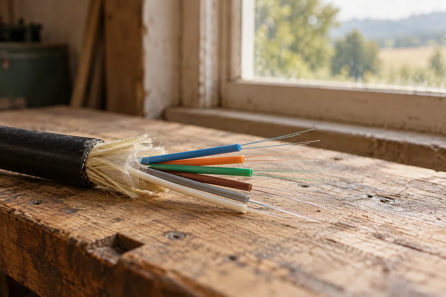
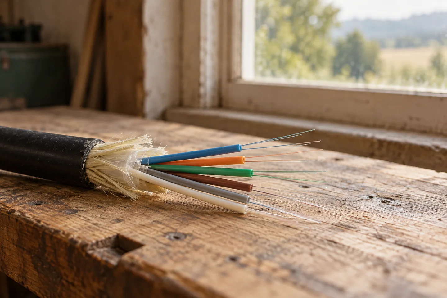 A window-side workbench with the end of a fiber optic cable and thin, differently colored buffer tubes fanned outView original
How universal is the 12-color order?
The TIA-598 order is widely adopted, but it is not a universal rule for every cable. FOA says TIA-598 sets the color code standard for fiber optics and that most manufacturers adopt and reference it. In the same paragraph it adds that there are many exceptions based on national standards, customer requirements or preferences. "Common" and "many exceptions" sit side by side in one sentence.
The TIA-598 fiber order is blue (1), orange (2), green (3), brown (4), slate (5), white (6), red (7), black (8), yellow (9), violet (10), rose (11) and aqua (12). Hexatronic's whitepaper says this scheme was formerly called the Bellcore standard and is the most recognized system worldwide. It also points out that the names follow US English, so slate is grey, rose is pink and aqua is turquoise. A drawing that says grey, pink and turquoise can therefore refer to the same positions.
According to FOA, the sequence follows the convention created for telephone wires, except that fibers are identified one by one rather than in pairs.
What if the same number carries a different color?
The same number gets a different color under a different scheme. DIN-0888, which Hexatronic calls the most common system in Germany, S12, introduced in 2012 by Skanova of Sweden, and Finland's FIN 2012 all assign other colors to the same twelve positions. The table below uses the values in FOA's comparison table, and they match the values in Hexatronic's whitepaper.
Scroll horizontally to view a wide table.
| Position | TIA-598 | DIN-0888 | S12 | FIN 2012 |
|---|---|---|---|---|
| 1 | Blue | Red | Red | Blue |
| 2 | Orange | Green | Blue | White |
| 3 | Green | Blue | White | Yellow |
| 4 | Brown | Yellow | Green | Green |
| 5 | Slate | White | Yellow | Grey |
| 6 | White | Grey | Grey | Orange |
| 7 | Red | Brown | Brown | Brown |
| 8 | Black | Violet | Black | Turquoise |
| 9 | Yellow | Turquoise | Violet | Black |
| 10 | Violet | Black | Orange | Violet |
| 11 | Rose | Orange | Turquoise | Pink |
| 12 | Aqua | Pink | Pink | Red |
Start with positions 1 and 2. Blue is fiber 1 in TIA-598, fiber 3 in DIN-0888, fiber 2 in S12 and fiber 1 in FIN 2012. Position 2 is orange in TIA-598, green in DIN-0888, blue in S12 and white in FIN 2012. Scan all twelve rows and you will not find a position where all four schemes use the same color. Some pairs do overlap: black at position 8 is shared by TIA-598 and S12, and brown at position 7 is shared by DIN-0888, S12 and FIN 2012.
Suppose a drawing says a cable follows S12 while the person at the splice remembers the TIA-598 order. Reading the blue fiber as number 1 would mean treating the real fiber 2 as fiber 1. This is a hypothetical calculated from the table, not a reported incident. The four schemes use the same twelve colors and differ only in order, so a wrong guess about the scheme produces no unfamiliar color and no visible hint that anything is off. A color name alone does not fix a number. The number is fixed only when the name of the scheme comes with it.
How do the markings continue past twelve?
Beyond twelve tubes or fibers, the same twelve colors repeat with an added mark such as a stripe or a dashed line. All three sources describe this in similar terms. The details of the mark are where they diverge.
FOA says tubes 13 to 24 repeat the colors with a black stripe (black itself takes a yellow stripe), tubes 25 to 36 use an orange stripe and tubes 37 to 48 a green stripe. In the TIA-598 tube table in Prysmian's guide, tubes 13 to 24 carry a black stripe and tube 20, the black one, a yellow stripe. Tubes 25 to 36 carry a red stripe, and tube 37 is blue with a green stripe. So one source gives an orange stripe for tubes 25 to 36 and the other gives red. I cannot say which one matches the standard because I could not read it. Manufacturers may mark differently, so the tube color chart should come from the manufacturer's own documents.
For tubes holding 24 fibers, Prysmian distinguishes two designs. One uses binder threads to split the fibers into groups: a blue thread group holds fibers 1 to 12 and an orange thread group holds fibers 13 to 24. The other makes all 24 fibers individually identifiable. Fibers 1 to 12 use the standard twelve colors, and fibers 13 to 24 repeat them with black dashes, except that fiber 20 is an uncolored fiber with a black dash. FOA also notes that tubes holding more than 12 fibers use binder tape to separate fibers into groups.
Hexatronic explains why one position is treated differently. In TIA/EIA-598, fiber 20 is clear, because a black ring mark would not show on a black fiber. In DIN-0888 black is position 10, so fiber 22 is the clear one. If you remember fiber 20 as black, that does not match this marking.
Here is one example of how the same number reads differently. Suppose you are looking for fiber 6 in tube 14. Under the TIA-598 table in Prysmian's guide, tube 14 is orange with a black stripe and fiber 6 inside it is white. Under Hexatronic's S12 table, tube 14 is blue with an added mark and fiber 6 is grey. The numbers are the same and both colors you need to find have changed.
Do the counting direction and layers matter too?
Yes. Hexatronic's whitepaper shows a separate counting direction for each standard. For TIA/EIA-598 and S12 it says that in cable designs with several layers of tubes, counting starts in the innermost layer. You can read a tube's color and stripe correctly and still not know where counting starts or which way it runs, because a color chart does not say. That comes from the manufacturer's cross-section drawing or the project drawings.
Are jacket and connector colors the same convention?
No, they are a separate system from fiber colors. In the jacket colors FOA lists for TIA-598, yellow marks single-mode (OS1, OS1a, OS2), orange marks OM1 and OM2, and aqua marks laser-optimized 50/125 multimode (OM3, OM4). For connector bodies, blue marks single-mode PC and green marks single-mode APC. A yellow patch cord tells you the fiber type. It has nothing to do with whether the fiber inside, number 9, happens to be yellow. FOA also notes that outdoor cables are generally black for protection against UV light, with the markings printed on the jacket. When the jacket is black, its color carries no information and the printed legend has to be read.
What should be checked before splicing?
Five checks, in order, are enough. The table below is DMS.Labs' proposed order, built on the facts above. It is not a standard or a manufacturer requirement.
 A desk seen from above with a notebook of small colored dots in rows and a pencil beside a splice trayView original
Scroll horizontally to view a wide table.
| Step | What to confirm | Where to confirm it | If it is missing |
|---|---|---|---|
| 1 | Name of the color scheme | Cable print legend, datasheet, design drawing | Ask the designer or manufacturer for the document before work starts |
| 2 | Tube colors and stripe rules | Manufacturer's color chart | Check especially when there are more than 12 tubes |
| 3 | Fibers per tube and how fibers beyond 12 are marked | Manufacturer's color chart | Tell binder threads from dashes |
| 4 | Where counting starts and which way it runs | Manufacturer's cross-section drawing, project drawings | With several layers, confirm whether counting starts from the inside |
| 5 | Color scheme of the cable at the other end | Drawings for both cables | Make a separate number-to-number table for the two cables |
Step 1 needs no equipment. Look for the scheme name in the cable print and the datasheet; if that step comes up empty, I would not trust the rest. If the cable consists only of products from one manufacturer in the TIA-598 family and the drawing names the scheme, steps 2 to 4 should go quickly. If cables from overseas manufacturers are mixed in, or the drawing does not name the scheme, I would stop work at step 1.
What should the record say after splicing?
I propose that a record should not list colors alone. It should carry the scheme name, the tube position, the fiber number and the connection at each end. FOA says the usual practice at a splice is to join like colors so the color code stays continuous along the whole cable run. For two cables that use the same scheme, that is enough. If the two cables use different schemes, the same color may not be the same number, so write the correspondence between colors and numbers separately.
FOA's FAQ describes the usual practice as documenting every fiber in every cable with a fiber designation, color code and connections on each end. Adding the scheme name and tube position is DMS.Labs' suggestion. Someone who never saw the drawing should be able to find the same fiber from the record alone.
What to read next
The scope of field training is described on the DMS.Labs FTTx field training page, which is provided in English. Measurement and records after splicing are covered in Before the Loss Number: Making a Fiber Test Result Trustworthy, and the checks for reopening a closure are in First Sealing Is Not the Finish Line: Keeping a Splice Closure Watertight at Re-entry.
Sources consulted
Checked on October 20, 2026. Markings differ between products and cables, so follow the manufacturer's document for the version you actually use. The two photographs in this article are AI-generated illustrations, not records from a real site.