A number appears on the tester and the job can feel finished. Yet the number is only useful if we can say which section of fiber it describes, how it was obtained, and what limit it is being compared against. The quality of a fiber test is decided as much by the preparation and the record as by the moment the test button is pressed.
This is a practical checklist for planning and reviewing a test, not a substitute for a customer's acceptance specification, a network design, an applicable standard, or the instructions for a particular instrument. The permitted loss, test wavelength, method, and reporting format must come from those documents. The point here is to make the measurement conditions visible before anyone calls a link good or bad.
1. Write down the question before choosing the instrument
“Measure the fiber loss” does not yet define the work. Are we verifying end-to-end insertion loss? Looking for the location of a troublesome event? Checking received optical power on a live service? These are different questions, and the same unit on two displays does not make their answers interchangeable.
An optical loss test set, or OLTS, uses a light source and power meter to evaluate insertion loss from one end of a link to the other. An optical time-domain reflectometer, or OTDR, uses backscatter and reflections to characterize sections and events along a fiber. Fluke Networks describes a complementary strategy: use OLTS for the basic link-loss assessment and OTDR for the location and characterization of individual splices, connectors, and other events. An OTDR's displayed total loss is not an unconditional replacement for a specified OLTS acceptance test.
A useful one-sentence test plan says: “Between these two endpoints, at these wavelengths, using this method, we will compare the result with this loss budget.” If that sentence cannot be written, the test boundary may still be ambiguous. In an FTTx network with splitters and several connection points, verify that the section in the drawing is the section connected to the instrument. Otherwise a plausible number may answer the wrong question.
2. Inspect the surfaces before setting a reference
Assuming that a test lead or instrument port is clean is an easy way to build an unreliable result. Fluke Networks advises inspection of every end face before mating, including brand-new connectors and factory-terminated products. EXFO's OTDR user guide likewise directs the operator to inspect connectors and clean them when necessary before connection. Contamination can disturb the measurement and can damage a mating surface.
The disciplined sequence is inspect, clean if needed using a suitable method, inspect again, and then connect. Cleaning blindly over and over is not a substitute for inspection. A wrong connector type or a damaged ferrule is not a speck of dust. Include both ends of the test reference cords as well as the actual network connection. A clean instrument port does not compensate for a dirty link connector.
The reference is part of this same chain. If the reference for an OLTS test was set with one lead arrangement and the test cords or connections later change, check whether the comparison remains valid under the specified method. Save which reference method and cords were used. “Reference set” is less informative than a record that lets another engineer understand precisely how it was set. When measurements are repeated, that distinction can explain an apparent improvement or deterioration that did not happen in the installed fiber at all.
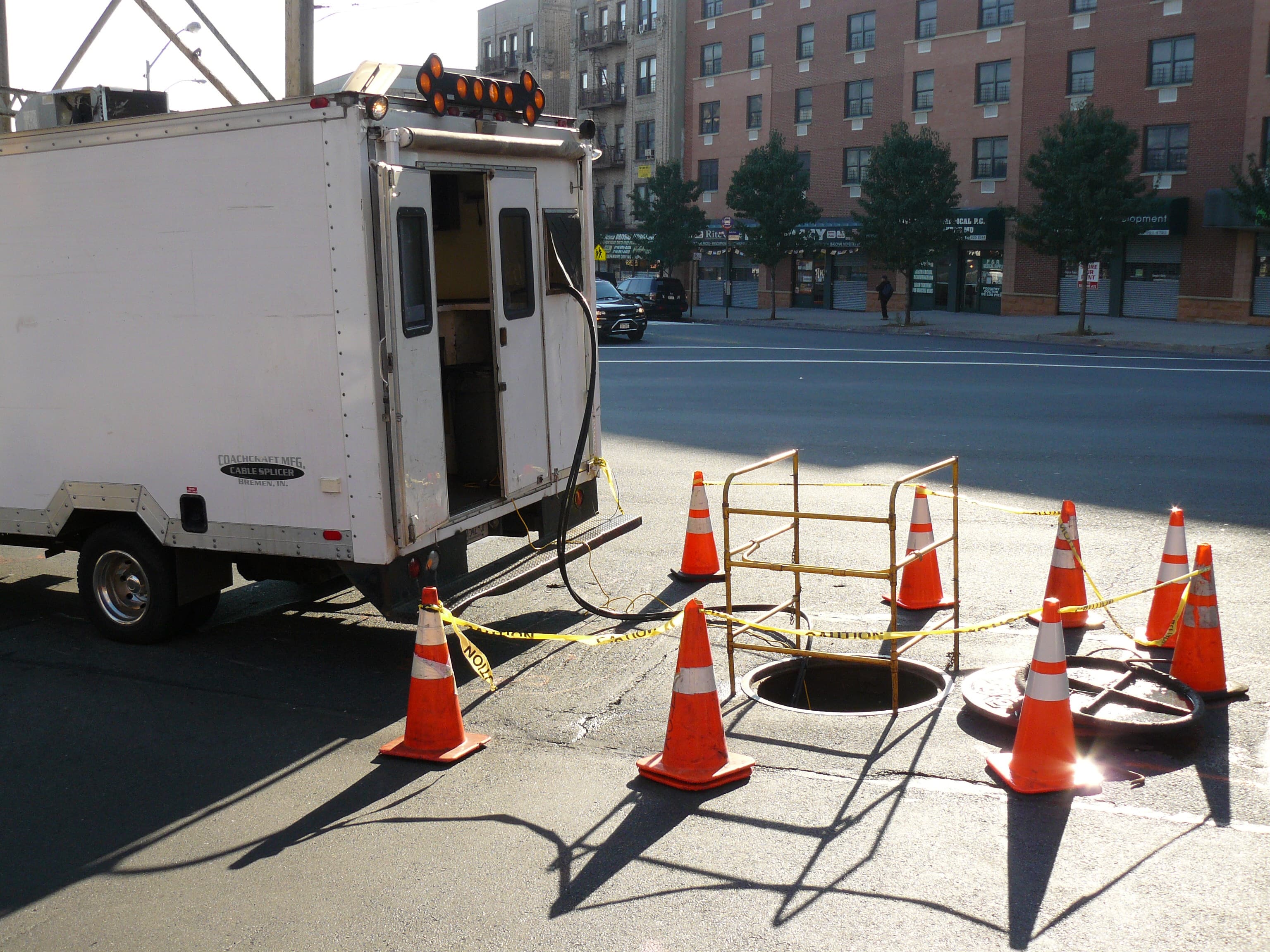
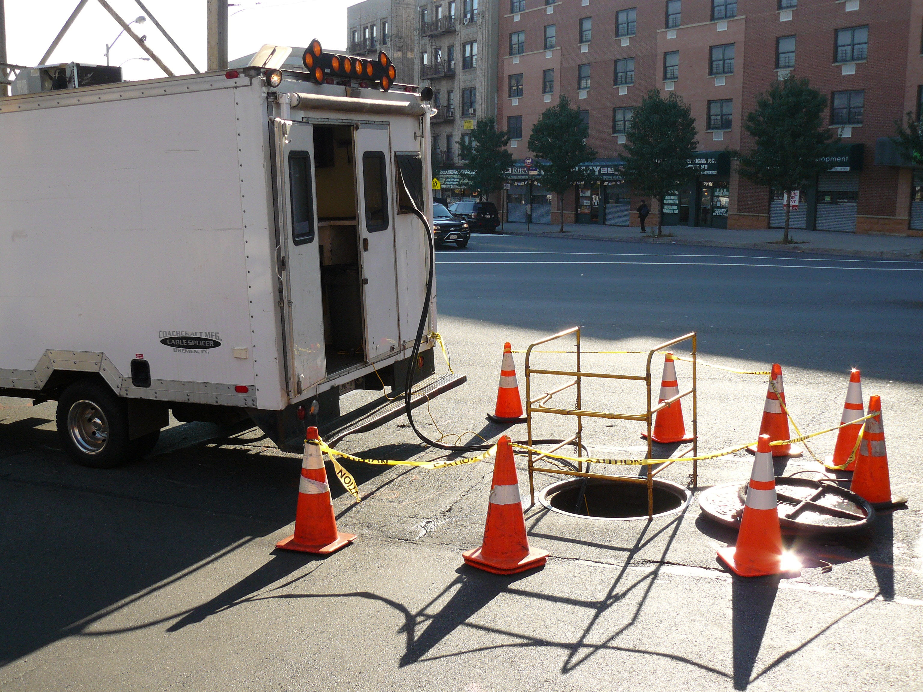 A real underground fiber splice work area prepared for accessView original
An actual fiber-splicing photograph, not a record of this article's project or site. Photo: Dhaluza, Wikimedia Commons, CC BY 3.0. Original aspect ratio retained; no content alteration.
3. Do not leave the first and last connector outside the OTDR story
A strong test pulse and its reflections can make nearby events hard to distinguish. A launch fiber between the instrument and the link gives the OTDR room to recover and allows the first network connection to be characterized. EXFO's application note on launch fibers explains that a receive fiber at the far end can make the final connector visible for loss and reflectance assessment as well.
The check is not merely whether a launch lead is present. Confirm that its fiber type and connector match the fiber under test, that its length suits the selected pulse width and event spacing, and that its own end faces are inspected. The instrument's link definition must place the actual network boundaries correctly. Otherwise the first or last connector can be omitted from the analyzed link, or a lead event can be mistaken for a network event.
Automatic OTDR analysis saves time, but it is not a reason to discard the trace. Keep the acquisition wavelength, pulse width, range, and event positions with the original trace. A shorter pulse can help resolve near-end events, while a longer distance or a high-loss section may call for a different setting. EXFO's beginner guide recommends checking with other pulse widths for an event that automatic settings may have missed. When a result looks odd, revisit the setup and the physical connections before replacing a network component on the strength of one screen.
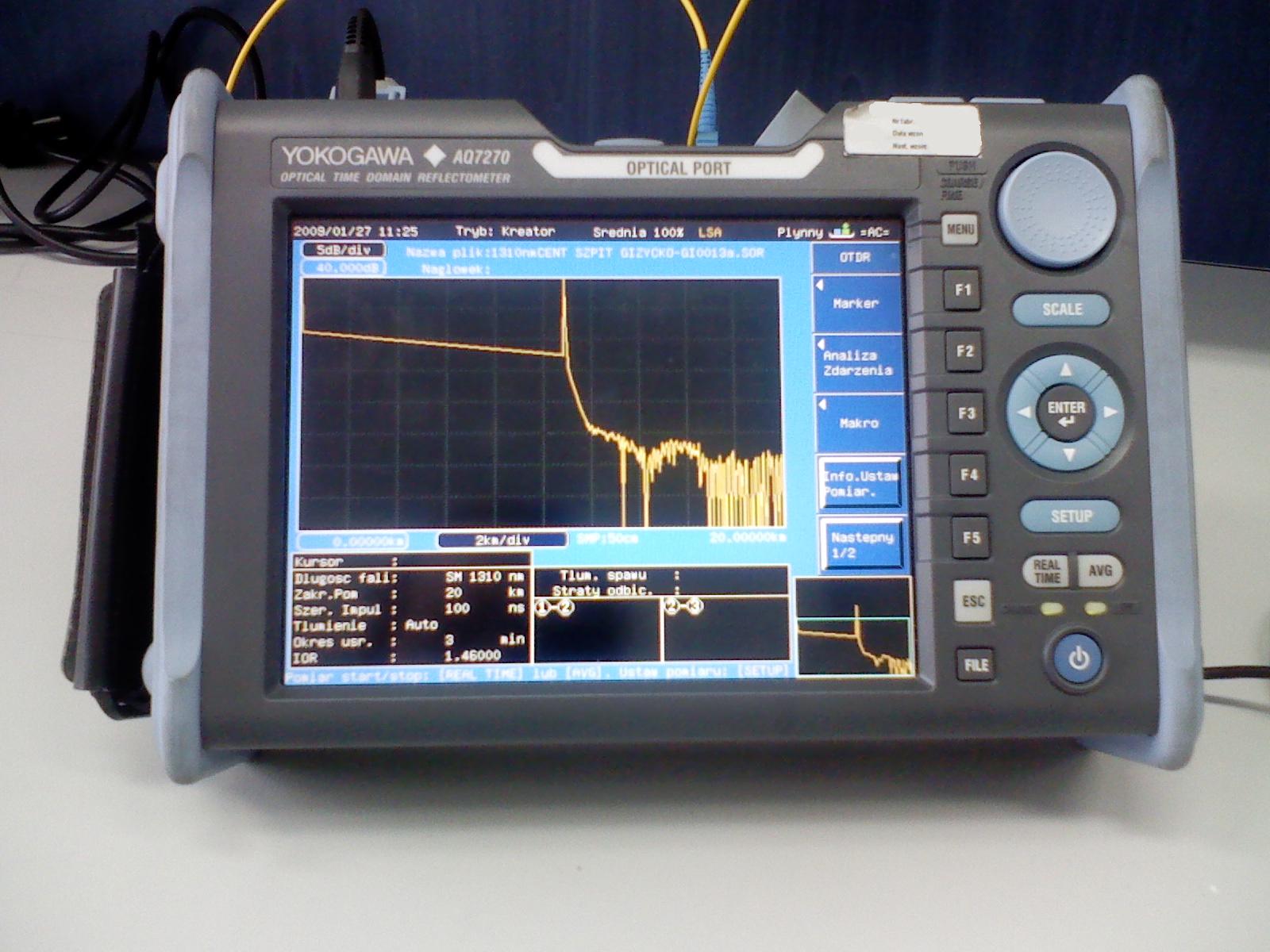 An actual Yokogawa AQ7270 OTDR on a calibration standView original
This is a photograph of an OTDR on a calibration stand, not a field measurement for this article. Photo: Electron, Wikimedia Commons, CC BY 3.0. Original aspect ratio retained; no content alteration.
4. A one-way “gain” is not a repair order
An OTDR trace can show a splice as an apparent gain. Fibers with different backscatter characteristics can make an event look like a “gainer” from one direction and an exaggerated loss from the other. EXFO's trace guide explains why bidirectional measurements are needed to determine the actual splice loss in this situation. Reopening a closure because of one unusual-looking event, without checking the reverse direction and the acquisition conditions, may be a misdiagnosis.
Whether bidirectional testing is required for a given link is defined by the project method and acceptance criteria. When it is used, save both directions and the way the values were compared. Establish a naming convention for fiber numbers and endpoints before testing so that the A-to-B and B-to-A files cannot be accidentally paired with different fibers. An orderly record matters most when the person investigating a later fault was not present during installation.
After an OTDR helps locate a problem, do not assume that the end-to-end insertion-loss requirement has been met. If the acceptance procedure calls for an OLTS result, perform that test too. The tools answer related but distinct questions. “Which one is better?” is less useful than “Which result is required for this decision, and what can the other tool add?”
5. Preserve the conditions along with the result
A pass icon alone is a weak handover. Link identifier, endpoints, fiber number, date, instrument and calibration status, test wavelengths, reference-setting method, test cords, launch and receive conditions, and original result files provide a much more useful package. The exact required fields vary by project, so this is a starting checklist rather than an official reporting form. If a borderline result was retested, record what changed between attempts.
Suppose a high-loss reading improves after connector cleaning. Keep the reason for the retest and the before-and-after conditions, not only the final number. That distinguishes an observed improvement from a confirmed cause. Conversely, if a test lead changed and the reference was not renewed as required, placing the two numbers side by side as if they were measured under identical conditions is misleading. The chain of evidence is what makes a result usable beyond the person holding the instrument.
Before signing off, ask five plain questions. Which link did we test? Which budget and method define acceptance? Were the first and last connections included? What happened to any unusual event when measured from the other end? Could another engineer open the original files and reach the same conclusion? A measured value becomes a maintenance asset only when those answers travel with it.
Sources
- Fluke Networks, OLTS & OTDR: A Complete Testing Strategy, on the complementary roles of the instruments and end-face inspection.
- EXFO, Guide to Using and Selecting the Right Launch Fibers for OTDR Test Sets, Application Note 298, on launch and receive fibers and the link boundaries.
- EXFO, A Beginner's Guide to OTDR Testing, on pulse width, event interpretation, and bidirectional measurements.
For an actual installation, use the network owner's specification, the instrument manual, and the current applicable standards as the controlling documents.