MPO polarity is the agreement that makes a transmit fiber at one end of a channel land on a receive position at the other. A Method describes the combination of parts across the whole channel. A Type describes how one trunk, adapter or cord maps fiber positions. A part labelled Type A is not automatically Method A, so choose one Method per channel, keep it from end to end, and check every label against that Method's table.
Based on references as of October 20, 2026.
Learning objectives
-
Separate a Method from a Type.
-
Read where position 1 arrives for each Type.
-
Find the part that breaks the Method in an order or test record.
Is Method A the same as Type A?
 Is Method A the same as Type A?View original
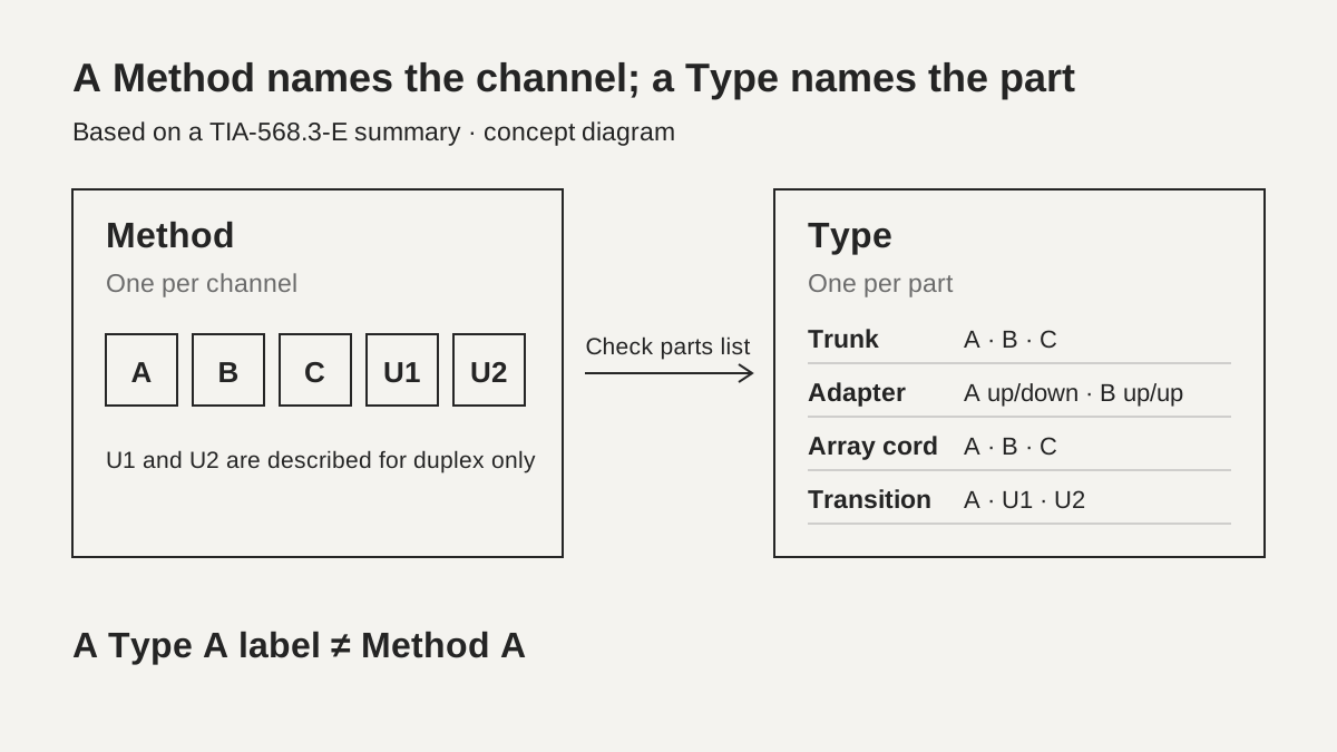
No. A summary of ANSI/TIA-568.3-E published by the TIA Fiber Optics Tech Consortium (FOTC) lists five sample array polarity methods, A, B, C, U1 and U2. It warns that the methods may not be interoperable and recommends choosing one in advance and using it consistently across an installation. In the same summary, a Type is a separate name given to each trunk cable, adapter, patch cord and transition. Method A uses a Type A trunk, yet one end of the same channel carries a Type B array cord. Reading a Type B label as proof of Method B can therefore be wrong.
The names overlap for a simple reason. A Method names a channel design and a Type names a part specification, and both use the letters A, B and C. An order that lists a Type A trunk with a Type B cord can describe a Method A array channel, while another order may use Type B to mean the trunk of a Method B channel. When you meet a label, first ask whether it names the channel or the part. Then compare the complete parts list with the Method table.
This lesson is document-reading practice. The text of TIA-568.3-E itself was not available for review, so the FOTC summary was compared against manufacturer technical documents. Field testing is carried out by authorized personnel following approved procedures and the instrument manual. Nobody should look into a port to find which side is transmitting.
-
Method: parts combination for the whole channel
-
Type: fiber mapping of one part
-
A Type A label does not mean Method A
Where does position 1 arrive?
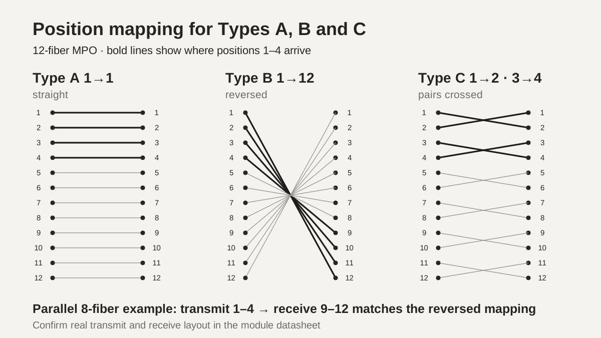
Type A sends position 1 to position 1, Type B sends position 1 to position 12, and Type C swaps each adjacent pair so position 1 arrives at position 2. Fluke Networks describes these three mappings for a 12-fiber MPO in a document dated November 12, 2025. A Type A trunk has a key-up connector on one end and key-down on the other, so position 1 meets position 1. A Type B trunk is key-up on both ends and sends 1 to 12. A Type C trunk flips each pair inside the cable, so 1 goes to 2 and 2 goes to 1. The key is the raised tab on the connector, and the white dot on its side marks position 1.
 Position mapping for Types A, B and CView original
Scroll horizontally to view a wide table.
| Type | Trunk end keys | 12-fiber mapping | How to read it |
|---|---|---|---|
| Type A | up / down | 1→1, 2→2 … 12→12 | straight |
| Type B | up / up | 1→12, 2→11 … 12→1 | reversed |
| Type C | up / down | 1→2, 2→1, 3→4, 4→3 … | pairs crossed |
This table helps when you must decide which applications a trunk can serve. According to the same Fluke document, an 8-fiber parallel application transmits on positions 1–4 and receives on positions 9–12. Transmit 1 must reach receive 12 at the far end, so a reversed mapping fits, while a straight mapping alone sends transmit to transmit. Type C sends 1 to 2, another transmit-side position, and also fails. That is consistent with Fluke not recommending Type C for parallel optics; reading the table this way is DMS interpretation. Confirm the real transmit and receive layout of a module in its datasheet.
Duplex applications read the other way. In Fluke's duplex example, position 1 is transmit and position 2 is receive, so the pair crossing of Type C already connects transmit to receive inside the cable. Type A sends 1 to 1, which means transmit lands on transmit and needs one more reversal somewhere. In Method A, an A-A duplex cord at one end supplies that reversal.
-
Type A: 1→1 straight
-
Type B: 1→12 reversed
-
Type C: 1→2 pairs crossed
Which parts belong to which Method?
Each Method fixes a combination of trunk, adapter, transition and cord, and parts from different Methods must not be mixed. The FOTC summary lays out the five as follows. The duplex column covers channels using an MPO-to-LC transition, and the array column covers MPO-to-MPO channels.
Scroll horizontally to view a wide table.
| Method | Trunk and adapter | Duplex implementation | Array (MPO-to-MPO) implementation |
|---|---|---|---|
| Method A | Type A trunk, Type A adapter (key up/down) | Type A transition; A-B jumper at one end and A-A jumper at the other | Type A array cord at one end, Type B at the other |
| Method B | Type B trunk, Type B adapter (key up/up) | Type A transition; A-B jumpers at both ends | Type B array cords at both ends |
| Method C | Type C trunk, Type A adapter (key up/down) | Type A transition; A-B jumpers at both ends | Type B array cord at one end, Type C at the other |
| Method U1 | Type B trunk, Type A adapter (key up/down) | Type U1 transition; A-B jumpers at both ends | not described |
| Method U2 | Type B trunk, Type B adapter (key up/up) | Type U2 transition; A-B jumpers at both ends | not described |
Three features stand out. Method A uses different cords at the two ends. Fluke says this creates confusion in patching areas and forces stock of both cord types. Method B uses the same cord at both ends, which keeps selection simple, but the same document says one cassette typically has to be inverted, which makes port numbering confusing and calls for special labeling, and some manufacturers require two different cassettes. Finally, Methods U1 and U2 arrived with TIA-568.3-E, published in September 2022. They use a Type B trunk with A-B cords, and the TIA summary describes them only for duplex implementations.
U1 and U2 differ in the fiber arrangement inside the transition and in adapter orientation. Siemon explains that U1 uses key up/down adapters, which lets it support single-mode angled physical contact (APC) end faces. Fluke explains that U2 supports direct breakout from a high-speed parallel port to several duplex ports, whereas U1 needs extra non-standard A-A cords for the same breakout. These are manufacturer advantages, so check the product datasheet before choosing.
-
Choose parts only from one Method's table
-
Separate duplex and array implementations
-
U1 and U2: described for duplex only
What if the references disagree?
When references disagree, read the standard summary and each manufacturer document with its stated conditions, and hold judgement on whatever remains unconfirmed. Three apparent conflicts appeared in the references compared for this lesson.
First, the cord in Method A. Fluke's November 2025 document says an A-A duplex cord is needed at one end. Its January 2026 document says a Type A array cord is used at one end and a Type B array cord at the other. These do not conflict. The first describes a duplex implementation with an MPO-to-LC transition, and the second describes an MPO-to-MPO array implementation. The TIA summary also lists the two separately. When you meet the word cord, first ask whether it means an LC duplex cord or an MPO array cord.
Second, the transition name for U2. In its U2 paragraph, Fluke's November 2025 document names a Type U1 transition, while the TIA FOTC, Siemon and CommScope references name a Type U2 transition. This lesson follows those three and records the Fluke sentence as an inconsistency. Whether it is a slip or carries another meaning was not confirmed.
Third, adapter orientation in Method B and single-mode links. The TIA summary lists key up/up adapters for the array implementation of Method B. Fluke's November 2025 document says a key-up to key-up approach cannot mate the 8-degree APC end faces properly, and its January 2026 document describes a variant with Type A adapters for APC and calls it Modified Method B. Fluke also says all single-mode MPO connectors use APC, so a single-mode channel needs the adapter orientation checked against the manufacturer's design documents instead of trusting the Method name.
Fluke's three documents come from one manufacturer, so they are not counted as three independent confirmations. The evidence for this lesson is one standard summary, three different manufacturers, and Fluke's testing-oriented pages.
-
Cord: LC duplex or MPO array?
-
U2 transition name: record the inconsistency
-
Single-mode: check adapter orientation in the design
Where does this hypothetical order go wrong?
It matches neither Method A nor Method B. Suppose a training order for 12 fibers lists a Type A trunk, Type B array cords at both ends, and Type A adapters. Method A allows a Type B cord at only one end, and Fluke's January 2026 document says only one Type B cord is allowed in a link under TIA standards. Method B would need a Type B trunk, so that is not this configuration either. Fluke says a polarity tester can flag the mistake of installing Type B cords at both ends on Type A trunks. Every part name and quantity in this order is an assumption and not a real product.
There are two ways to correct it. Changing one cord to Type A produces a Method A array channel. Changing the trunk to Type B moves toward Method B, but then the adapters and cords must also follow the Method B table. Which route is right depends on installed equipment, stock and application specifications, and the design owner decides. Even when a test reports a polarity mismatch, do not replace cable immediately. First identify which part differs from the design by checking the Method table. Fluke advises settling polarity in the design phase and notes that pre-terminated assemblies are often made to order and difficult to return.
Check pinning at the same time. Fluke says MPO ports on active equipment are male, with pins, so a cable plugged directly into equipment must be unpinned. The TIA-568.3-E recommendation as summarized by Siemon pins both ends of the trunk and leaves the MPO inside transitions and the later equipment array cords unpinned. A wrong pin configuration prevents mating even when polarity is correct, so record it on the same line as the polarity table.
-
Method A: one Type B cord per link
-
Method B: assumes a Type B trunk
-
Record pinning separately from polarity
What goes into the handover record, and what was not checked?
Write the following on one page: Method name, Type of each part, adapter orientation, pinning at both ends, fiber count (8 or 12), polish (UPC or APC), the expected position mapping and the tester result. State the expected mapping first, for example transmit 1 arriving at receive 12, and place the tester's reported mapping beside it. Record the tester model and software version too. Fluke describes its testers as able to check polarity on cords, permanent links and channels; that is a manufacturer statement, and this lesson did not reproduce it with an instrument.
Some parts let you change key orientation in the field. Fluke names US Conec's MTP PRO and Panduit's PanMPO as UPC multimode connectors whose key position can be changed, and adds that APC connectors cannot change polarity because of the angled end face. When such parts are used, the label and the actual key orientation can differ, so note the change in the record.
State what was not verified. The text of TIA-568.3-E and any revision since, IEC requirements, manufacturer-specific method names and real tester behavior were not checked in this lesson. The TIA FOTC and CommScope dates are those displayed in search results, and the pages themselves showed no date. Fluke's MPO learning page carries no date, and the check date is October 20, 2026. No original figure or table was copied; the position mappings were redrawn independently. Final acceptance still needs tests that match the applicable specification and the customer requirement.
-
Method, Types, orientation, pins and polish on one page
-
Expected mapping beside the tester result
-
State the unverified scope
Checklist
-
Were the Method name and each part Type written separately?
-
Do all parts sit in one Method's table?
-
Were adapter orientation and pinning recorded at both ends?
-
Was the expected position mapping compared with the tester result?
-
Was adapter orientation on single-mode APC channels checked against the manufacturer design?
Review questions and answers
1. If a label shows Type B, is it a Method B channel?
Answer: No. A Method is the combination for the whole channel and a Type names one part. The array implementation of Method A also uses a Type B cord at one end.
2. With transmit on positions 1–4 and receive on 9–12, why does a Type C trunk not fit an 8-fiber parallel link?
Answer: Type C sends 1 to 2, so transmit lands on a transmit-side position. The application needs a reversed mapping such as 1→12. Confirm the module's real layout in its datasheet.
3. May U1 or U2 be chosen as the Method for an MPO-to-MPO array link?
Answer: No. The TIA summary reviewed here describes only duplex implementations for U1 and U2. For an array link, confirm Method A, B or C in the design document.
Sources and versions
-
TIA FOTC: ANSI/TIA-568.3-E Optical Fiber Cabling and Components Standard · search-displayed 2023-10-24; standard published 2022-09
-
Fluke Networks: Getting 12- and 8-Fiber MPO Polarity Right · 2026-01-06
-
Fluke Networks: Fiber Polarity Basics for Duplex Applications · 2025-11-12
-
Fluke Networks: Multi-fiber Push On (MPO) Connectors · undated, checked 2026-10-20
-
Siemon: ANSI/TIA-568.3-E Introduces New Polarity Methods · 2022-10-27
-
CommScope: Standards Updates for Optical Fiber · search-displayed 2023-07-02