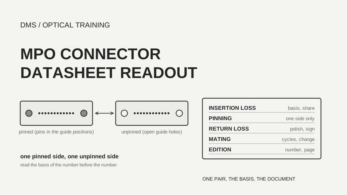
The insertion loss on an MPO connector datasheet can only be compared once you know whether it is a value against a reference connector, a random mating value, a test value of a finished trunk, and for what share of samples it holds. A pin must sit on exactly one side of every mated pair, but which side carries the pins follows a different convention from one document to the next, and a mating cycle count means little unless the allowed loss change sits on the same line. In the 12-fibre single-mode lines that were read, the maximum insertion loss of one pair was printed as 0.25 dB to 0.35 dB for low loss grades and 0.70 dB for the Senko standard grade. A link loss budget should record which value of which document was used.
As of November 13, 2026, based on the documents listed under Sources.
Learning objectives
-
Split an MPO insertion loss line into the kind of value (typical, mean, maximum), the partner condition (reference, random mating, finished trunk) and the share of samples it covers.
-
Mark the pinned and unpinned side at every mating plane, and align the pinning conventions of different documents on one drawing.
-
Read return loss and mating cycles together with polish type, fibre count and allowed loss change, and when two documents of one maker disagree, record both values with page number and edition.
What is the basis of an MPO insertion loss number?
Insertion loss is the value of one mated pair, but the same number points to a different condition depending on whether the partner is a reference connector, a randomly chosen connector, or a finished assembly. The Senko MPO-PLUS standard connector datasheet (702 and 712 series, no document date printed) gives the 12-fibre single-mode low loss grade as 0.10 dB typical and 0.25 dB maximum, and a note under the table says the basis is a master grade jumper mated at random with a low loss connector. The Senko technical brochure (E-1.0), page 9, says the values are per single fibre. It adds that the 0.25 dB maximum of the low loss grades holds for 95% of all fibres and is reached only with Senko's recommended reference jumper, polishing process and test method. Reading the remaining 5% as free to exceed that maximum is a DMS interpretation.
The Rosenberger-OSI MTP (MPO) n x 12 fibre datasheet (revision 008, dated March 30, 2026) lists maximum values against a reference connector by IEC 61300-3-4 method B and by quality grade. For single-mode and multimode Elite ferrules, the BASIC grade is 0.35 dB and the PURE grade is 0.25 dB. A multimode standard ferrule for more than 12 fibres exists only as BASIC at 0.60 dB. The PURE grade also carries an application limit for random mating of 0.15 dB on average, with US Conec named as the source. One datasheet therefore holds both a maximum against a reference and a random mating average.
The Corning EDGE8 solutions document (LAN-2655-A4-BEN, footer November 2026) gives the ultra low loss mated pair for MPO/MTP as 0.25 dB or less for multimode and 0.35 dB or less for single-mode, and says this does not apply to angled (APC) polish. A note under the trunk table says the connector insertion loss values are for reference because Corning tests the complete trunk including both MTP connectors. A number that looks like one connector can therefore be guaranteed by a whole-assembly test. Because a partner connector in the field is rarely a reference piece, the random mating line or the finished trunk line is closer to the starting point of a budget, which is a DMS interpretation.
Scroll horizontally to view a wide table.
| Document | 12-fibre single-mode insertion loss | Partner or basis | Condition read in the notes |
|---|---|---|---|
| Senko standard connector datasheet | Typical 0.10 / maximum 0.25 dB (low loss) | Master grade jumper to low loss connector, random mating | No document date printed |
| Senko technical brochure E-1.0 (page 9) | Typical 0.10 / maximum 0.25 dB | Senko recommended jumper, polishing, test method | Per single fibre; maximum for 95% of fibres |
| Rosenberger n x 12 (revision 008) | Maximum 0.35 (BASIC), 0.25 (PURE) dB | IEC 61300-3-4 method B, against reference | PURE has a separate random mating average of 0.15 dB |
| Corning EDGE8 (LAN-2655-A4-BEN) | Mated pair 0.35 dB or less (OS2) | Mated pair value, not applicable to APC | Complete trunk is tested |
| RDM trunk cable (version 2.10/2023) | Mean 0.15 / maximum 0.30 dB | IEC 61300-3-4 | States that other test methods may give different values |
| XFS MPO/MTP module (no date printed) | Typical 0.1 / maximum 0.25 dB | IEC 61300-3-4 | Based on a 12-fibre connector |
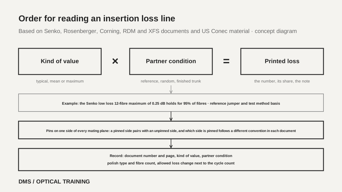 Order for reading an insertion loss lineView original
-
Write down the kind of value and the share it covers (95%, 97% and so on) before copying the number
-
Check from the datasheet wording whether the partner is a reference connector, random mating or a whole trunk
-
Put the per fibre or whole link basis, the document number and the date on the same line
What do you record when two documents of one maker disagree?
Even documents of one maker can disagree in a number or in the wording of a condition, and the safe habit is to write down both values with their page numbers instead of picking one. Senko prints the typical insertion loss of the 12-fibre multimode standard grade as 0.10 dB in the datasheet (702 and 712 series) and as 0.15 dB on pages 9 and 21 of the technical brochure E-1.0. The maximum is 0.50 dB in both, and the multimode low loss values of 0.08 dB and 0.25 dB match. Which document is current is not stated in either.
The Senko EZ-Way connector datasheet (752 and 753 series) mixes two conditions inside one document. Its first page says that single-mode premium low loss reaches a maximum of 0.35 dB when mated with other EZ-Way connectors or leading brand connectors. Its second page table gives 12-fibre single-mode low loss as 0.25 dB maximum, and the note under the table names a master grade jumper and low loss random mating as the basis. The first value reads as a connector against a real connector and the second as a connector against a reference jumper, and the two do not merge into one number.
Rosenberger also differs between two documents that cover different fibre counts. The minimum return loss of the single-mode PURE grade in APC is 70 dB in the 12-fibre document (revision 008) and 60 dB in the 16-fibre document (revision 003, dated November 28, 2024). These are separate product documents, so calling it a contradiction would be wrong, but copying the 12-fibre value to a 16-fibre part could be a mistake. The RDM trunk cable datasheet prints version 2.10/2023 on page 1 and version 2.11/2023 on pages 2 to 4 of one file. For a file like that, copy the number together with its page number.
Scroll horizontally to view a wide table.
| Documents | One value | The other value | How to read it |
|---|---|---|---|
| Senko datasheet against brochure (typical insertion loss, 12-fibre multimode standard) | 0.10 dB | 0.15 dB | The 0.50 dB maximum is the same, and which is current is not stated |
| Senko EZ-Way first page against table (single-mode low loss maximum) | 0.35 dB (mated connection) | 0.25 dB (reference jumper basis) | The condition wording differs, so do not read them as one value |
| Rosenberger 12-fibre against 16-fibre (PURE single-mode APC minimum return loss) | 70 dB | 60 dB | Separate documents for different fibre counts |
| One RDM trunk cable file | Page 1 version 2.10/2023 | Pages 2 to 4 version 2.11/2023 | Two edition marks in one file |
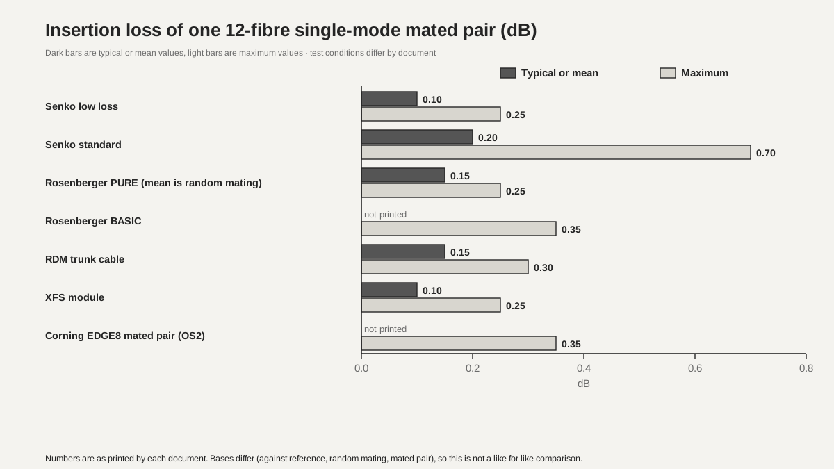 Comparison of 12-fibre single-mode insertion lossView original
-
Dark bars are typical or mean values as printed, and light bars are maximum values
-
Test conditions differ by document, so this is not a like for like performance comparison
How are pinned and unpinned connectors paired?
An MPO mating plane needs one pinned and one unpinned connector, and which side carries the pins follows a different convention in different documents. The Senko technical brochure says an MPO connection can be made only between a male connector with two alignment pins and a female connector with alignment holes. The Rosenberger datasheet also separates male with pins from female without pins and says gender can be changed according to US Conec document AEN-1405. The same document adds that polarity cannot be changed on 8 degree angled polish (APC) and only on flat polish (PC).
The US Conec MTP PRO material (no date printed) says there is no normative requirement for pinning and gives a rule of thumb: the side most likely to stay fixed behind a panel or inside an enclosure should be pinned. It explains that the MPO inside a breakout module is usually pinned, so a trunk backbone is often unpinned on both ends. It adds that a parallel optics device needs pins in the active device, so using like-ended equipment cords can force the trunk to change from unpinned to pinned. This is manufacturer material, and it sits inside the explanation of a product that sells pin change.
There is also a convention pointing the other way. The Corning EDGE8 document lists the 8-fibre trunk with pinned connectors on both ends and says it connects to modules and adapter panels. The MPO adapter on the back of the module is given with non-pinned codes (E6, E8). An extender trunk is unpinned on one end and pinned on the other, and a harness is to be Type-A polarity and non-pinned when it connects to a trunk, and Type-B polarity and pinned when it connects to a module. The FOA reference page also says a permanently installed backbone usually has pins and patch cords have none, and counts four types from the pin and key position combinations. That page is its author's explanation, so it is not counted at the same level of evidence as a manufacturer datasheet.
Scroll horizontally to view a wide table.
| Document | Fixed trunk | Module or equipment side | Line it rests on |
|---|---|---|---|
| US Conec MTP PRO material | Usually unpinned on both ends | MPO in a breakout module and parallel optics devices are pinned | Rule of thumb with no normative requirement |
| Corning EDGE8 | 8-fibre trunk pinned on both ends | Adapter on the back of the module is non-pinned | Harness: non-pinned Type-A to a trunk, pinned Type-B to a module |
| FOA reference page | Installed backbone usually pinned | Patch cords usually unpinned | Explanation by the page author |
| Senko, Rosenberger | Pinning chosen by order code | Gender changeable products are separate | Male has pins, female has none |
Pin parts also differ by fibre count. The Senko parts list gives the pin keeper for 12 and 24 fibres and the pin keeper for 16 and 32 fibres under different part numbers. The US Conec material gives the MT guide pin diameter for 12 fibres as 700 µm, and the Senko brochure gives the new pin diameter specification for 16 and 32 fibres as 0.55 mm. For pin retention the US Conec material quotes the IEC 61754-7 minimum of 19.6 N and states about 48 N for its own measurement, which is the maker's own measurement and was not confirmed by an independent test.
How is return loss compared together with polish type?
Return loss lines can be set side by side only when the polish type (flat PC or angled APC) and the kind of value (typical or minimum) match. The Senko datasheet prints typical return loss as 60 dB or more for single-mode APC and 25 dB or more for multimode, and the brochure says single-mode is 8 degree polish and multimode is flat polish. The Rosenberger 12-fibre datasheet gives minimum values against a reference by IEC 61300-3-6 method 1. Single-mode APC is 55 dB for BASIC and 70 dB for PURE, multimode flat polish is 30 dB for both grades, and multimode APC is 50 dB for BASIC and 55 dB for PURE.
The RDM trunk cable prints 35 dB or more for multimode and 55 dB or more for single-mode. The XFS module gives, for a 12-fibre connector, 65 dB or more for single-mode APC, 50 dB or more for single-mode UPC and 40 dB or more for multimode. The Corning EDGE8 trunk table prints the same phenomenon as reflectance, a negative number: minus 20 dB or lower for multimode and minus 65 dB or lower for single-mode. With the sign removed and the direction aligned, the Corning multimode value corresponds to 20 dB or more, the loosest of the documents read, and the XFS value of 40 dB or more is the strictest. Within the same Corning document, a trunk from MPO to an LC duplex uniboot connector gives the single-mode reflectance on the LC side separately as minus 35 dB or lower.
The reason multimode return loss spreads from 20 dB to 40 dB is not confirmed by the datasheets. A mix of polish type, test method and typical versus minimum is a plausible guess, which is a DMS assumption. The FOA reference page says the direction of the angle of single-mode and multimode APC polish, toward the key or away from it, appears not to be fixed by a standard, advises checking before mating, and says APC should be mated only with APC. That is the page author's explanation, and the standard text was not read.
Scroll horizontally to view a wide table.
| Document | Printed as | Single-mode | Multimode | Point to note |
|---|---|---|---|---|
| Senko datasheet | Typical return loss | APC 60 dB or more | 25 dB or more | Typical value only |
| Rosenberger 12-fibre (revision 008) | Minimum, against reference | APC 55 (BASIC), 70 (PURE) | Flat 30, APC 50 or 55 | Differs by grade and polish |
| RDM trunk | Return loss | 55 dB or more | 35 dB or more | Polish type given separately |
| XFS module | Return loss | APC 65, UPC 50 dB or more | 40 dB or more | Based on a 12-fibre connector |
| Corning EDGE8 trunk | Reflectance (negative) | Minus 65 dB or lower | Minus 20 dB or lower | Remove the sign and align the direction before comparing |
How do mating cycles and fibre count change the insertion loss line?
A mating cycle count becomes a pass criterion only when the allowed loss change is on the same line. The Senko datasheet and the EZ-Way datasheet give durability as 500 matings per TIA-568.3 and give no allowed loss change. Rosenberger prints a minimum of 500 cycles with an insertion loss increase of less than 0.2 dB, and XFS prints an insertion loss change of 0.2 dB or less for 500 mates. The RDM trunk cable prints mating cycles as less than 1000, and the document alone does not show whether that is a lower bound or an upper limit of a guarantee. The TIA-568.3 text was not read, so the test condition behind the Senko 500 is also unconfirmed.
The FOA reference page explains that MPO connectors are not as durable in mating as ceramic ferrule single-fibre connectors, so reference test cables can wear out early. When a loss measured with a reference cable suddenly rises, the wear of the reference cable should be suspected before the device under test. That is the page author's opinion and not a manufacturer test value.
With more fibres, the values grow even inside one product family. In the Senko datasheet, single-mode low loss is 0.10 dB typical and 0.25 dB maximum at 12 fibres, and 0.15 dB typical and 0.35 dB maximum at 24 and 16 fibres. Multimode standard is 0.10 typical and 0.50 dB maximum at 12 fibres, 0.20 and 0.50 dB at 24 fibres, 0.20 and 0.60 dB at 16 fibres, and 0.25 and 0.60 dB at 32 fibres. The RDM trunk cable raises the single-mode mean from 0.15 dB at 12 fibres to 0.20 dB at 24 fibres and the maximum from 0.30 dB to 0.45 dB. The Rosenberger 16-fibre document gives multimode random mating in application as 0.25 dB for 16 fibres and 0.35 dB for 32 fibres with the figures 89% and 80% attached; these read as sample shares, but the document does not define them. The 24-fibre multimode connector also differs in its spring in the Senko datasheet, which says a 20 N spring is supplied instead of the standard 10 N spring. A 12-fibre line should not be copied to 24 fibres.
Scroll horizontally to view a wide table.
| Document | Mating cycles | Allowed loss change | Note |
|---|---|---|---|
| Senko standard and EZ-Way datasheets | 500 (per TIA-568.3) | Not printed | A line whose pass criterion is unconfirmed |
| Rosenberger 12 and 16 fibres | At least 500 | Insertion loss increase under 0.2 dB | Both on the same line |
| XFS module | 500 | Insertion loss change 0.2 dB or less | Both on the same line |
| RDM trunk cable | Printed as less than 1000 | Not printed | Lower bound or upper limit is unclear |
Which value goes into a link loss budget?
The case here is a hypothetical training calculation and not a test of a real site or product. Assume a 12-fibre single-mode link with three MPO mated pairs and multiply the one-pair value of each document by 3. Multiplying a typical or mean value gives an expected loss, and multiplying a maximum value gives a conservative upper plan. Note in the record that summing maxima is a planning convention and not a rule of a standard.
Scroll horizontally to view a wide table.
| Document | One pair typical or mean (dB) | Three pairs (dB) | One pair maximum (dB) | Three pairs (dB) |
|---|---|---|---|---|
| Senko low loss | 0.10 | 0.30 | 0.25 | 0.75 |
| Senko standard | 0.20 | 0.60 | 0.70 | 2.10 |
| Rosenberger PURE (mean is random mating) | 0.15 | 0.45 | 0.25 | 0.75 |
| Rosenberger BASIC | Not printed | Not calculated | 0.35 | 1.05 |
| RDM trunk | 0.15 | 0.45 | 0.30 | 0.90 |
| XFS module | 0.1 | 0.30 | 0.25 | 0.75 |
| Corning EDGE8 (OS2) | Not printed | Not calculated | 0.35 | 1.05 |
The three-pair maximum totals run from 0.75 dB to 1.05 dB on the low loss grade lines and reach 2.10 dB for the Senko standard grade. Even for the same 12-fibre single-mode part, a different grade name changes the total by more than a factor of two. The calculation contains no fusion splice loss, fibre attenuation or margin. When a document that guarantees a finished trunk by testing (Corning) and a document that prints one-pair connector values share a cell, leave a note about that difference. Do not mix numbers printed by a datasheet with numbers calculated by DMS in one cell; mark the latter as a DMS calculation.
The limits of this material are also clear. The texts of IEC 61754-7, IEC 61300-3-4, IEC 61300-3-6, TIA-568.3, TIA-604-5 and Telcordia GR-1435 were not read. Whether each document is the current revision and whether it matches a product on sale now was not confirmed, and the Senko, XFS and US Conec documents print no date. The exact meaning of the RDM mating cycle mark and the Rosenberger share mark was not confirmed, nor why the two Senko documents differ on the multimode standard typical value, and no maker was contacted.
Checklist
-
Did you write whether the insertion loss line is typical, mean or maximum, whether the partner is a reference connector, random mating or a finished trunk, and the share it covers, with the document number and page number?
-
Did you mark the pinned and unpinned side at every mating plane on the drawing, and check whether the pinning of the bought trunk and of the module adapter are opposite?
-
Did you copy the sign, the polish type (flat or angled) and whether the value is typical or minimum of the return loss line in the same direction?
-
Did you check that the allowed loss change sits next to the mating cycle count, and write that the pass criterion is unconfirmed when it does not?
-
When two documents of one maker disagree or one file carries two editions, did you record both values with page number and edition instead of choosing one?
Review questions
1. Three mated pairs are made with the Senko 12-fibre single-mode low loss maximum of 0.25 dB per pair. What is the total, and may this value be used as an absolute upper limit?
Answer and explanation: The total is 0.25 dB times 3, which is 0.75 dB. However, the brochure note applies this maximum to 95% of all fibres and says it was obtained with Senko's recommended reference jumper and test method, so it is not an absolute limit. Summing is a planning convention, and the record should carry these conditions.
2. May a trunk that is unpinned on both ends be mated with a module adapter connector that is also unpinned?
Answer and explanation: No, because a mated pair needs exactly one pinned side. The US Conec material describes trunks unpinned on both ends with a pinned module side, while Corning EDGE8 describes trunks pinned on both ends with a non-pinned module adapter, so the conventions point in opposite directions. Before buying, mark the pinning at every mating plane on the drawing and use pin-changeable connectors where needed.
3. One datasheet prints only 500 matings, and another prints at least 500 matings with an insertion loss increase of less than 0.2 dB. In which can the pass criterion be confirmed?
Answer and explanation: Only in the second one. The first prints a count without an allowed change, so its pass criterion is unconfirmed, and the record should say that other evidence is needed.
Sources
-
Senko: MPO-PLUS standard connector datasheet (702 and 712 series, no document date printed) · pages 1–4 optical and mechanical data and order codes
-
Senko: MPO EZ-Way connector datasheet (752 and 753 series, drawing officially released June 20, 2024) · pages 1–3
-
Senko: MPO-PLUS technical brochure (E-1.0, no document date printed) · pages 2, 3, 9, 11, 21–23, 37
-
Rosenberger-OSI: MTP (MPO) connector n x 12 fibres technical data sheet (revision 008, dated March 30, 2026) · pages 1–2
-
Corning: EDGE8 solutions EMEA (LAN-2655-A4-BEN, footer November 2026) · pages 4, 16, 19, 20, 25, 30
-
RDM: MPO/MTP trunk cable datasheet (versions 2.10/2023 and 2.11/2023) · pages 1–4
-
XFS Communications: MPO/MTP module datasheet (no date printed) · pages 1–2
-
US Conec material (copy hosted by Fiber Instrument Sales): MTP PRO Solutions (no date printed) · pages 2–3
-
FOA reference page: testing cables with multifibre array connectors · pins and holes, polarity, testing sections