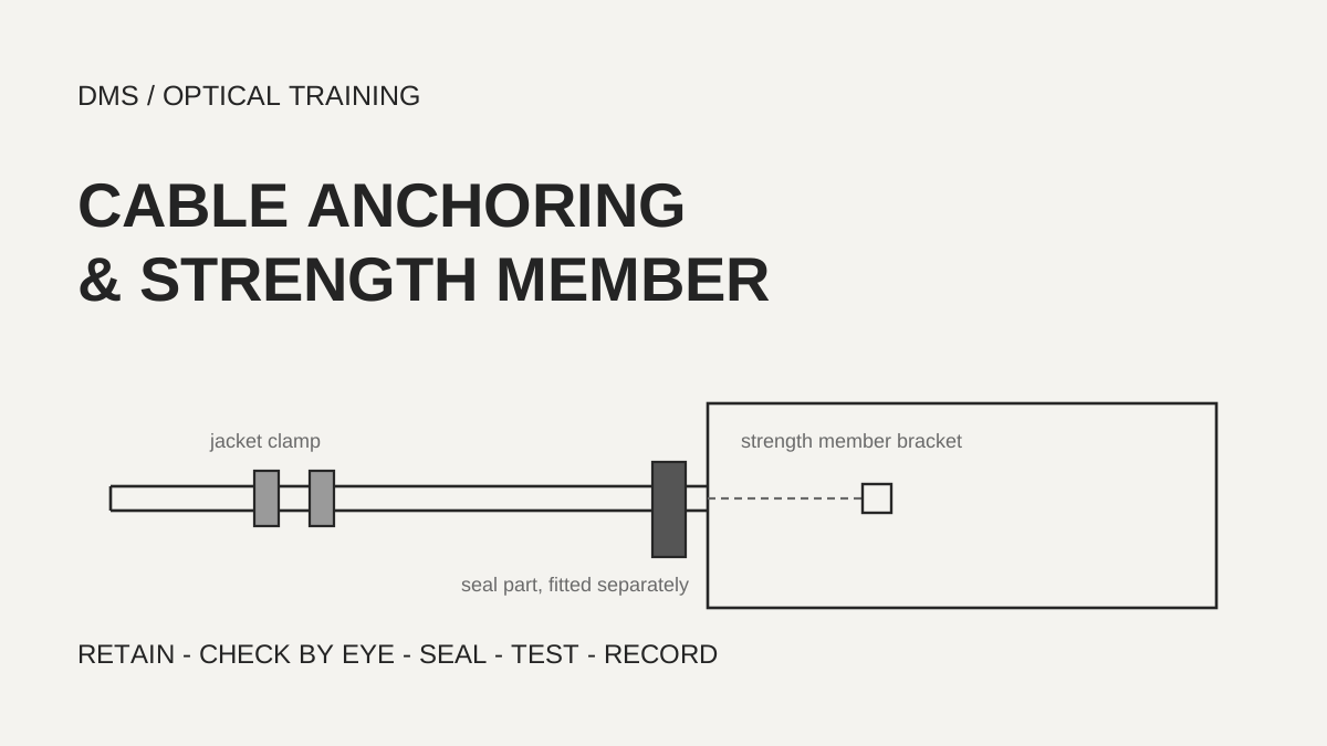
In a splice closure the cable is held by one part that grips the jacket and another that grips the strength member (the part of the cable used to hold it to the closure), and the seal is fitted as a separate step. The length of strength member to leave is 2.00 in, 1.5 in or 6 in depending on the closure, and each is measured from a different reference point, so do not carry one number from closure to closure. Follow the installation instructions of the closure in use.
Based on the manufacturer installation instructions and FOA material reviewed on October 27, 2026.
Learning objectives
-
Explain that cable retention, strength member termination and sealing are jobs for different parts.
-
Read a strength member length together with its reference point, and do not carry the number to another closure.
-
State the post-work checks and records that cover retention and sealing separately.
What holds the cable in a splice closure?
In the manufacturer instructions, retention is shared by two parts. One is a clamp or hose clamp that grips the jacket, and the other is a bracket or clamp that grips the strength member. The FOSC 450 D6 instruction (marked Tyco Electronics) has the installer fit the strength member into a dedicated bracket and tighten it, push that bracket into the jacket retention part, and then grip the jacket with a hose clamp. The Clearfield CraftSmart Splice Closure 250 manual also places the strength member in a Strength Member Bracket and secures the cable with a hose clamp in the same step. The AFL LG-600 instruction fixes the jacket to the frame with a hose clamp and holds the central strength member in a separate groove under a tie-down clamp.
The FOA closure page tells the installer to prepare cables in the exact sequence the manufacturer specifies, so that the cable is secured with adequate strain relief (a structure that keeps force on the cable from reaching the fibers) and the closure seals. It adds that the jacket and strength members may need special hardware from the closure manufacturer.
In all three instructions the retention parts and the sealing parts are separate parts. FOSC 450 D6 fits the gel end-piece after retention, and Clearfield compresses the gel block with a compression bolt after retention. Reading this as retention checked on its own and sealing checked on its own is DMS's interpretation. The documents do not state that the sealing part must never carry load.
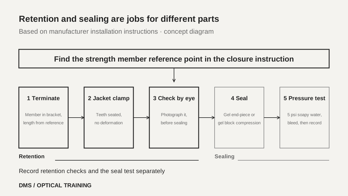 Cable retention and sealing are jobs for different partsView original
-
One part grips the jacket and another grips the strength member
-
The sealing part is fitted and checked separately from the retention parts
-
Part names and order follow the instruction of the closure in use
How much strength member is left, and where is it terminated?
Both the number and the reference point differ between documents. FOSC 450 D6 says to cut rigid strength members 2.00 in (about 51 mm) from the cable ring cut (the end of the sheath cut made around the cable). Clearfield CSC 250 says to cut the strength member 1.5 in (about 38 mm) above the cable jacket and to position the cable about 2.0 in above the top of the gel block. AFL LG-600 trims central strength members to 6 in (about 152 mm) from the sheath opening and leaves about 8 in (about 203 mm) of Kevlar on small cables. These three numbers are not the same length written three ways. They are different criteria for different closures.
Where the strength member is terminated depends on how many strength members the cable has and on its diameter. FOSC 450 D6 uses the center prong of the bracket for a central strength member, and for dual strength members it bends the middle prong out of the way and uses the two outer prongs. It says to choose the larger bracket for larger cables, but the original gives the guide only as "typically 288 and above" and does not say what is being counted. Clearfield CSC 250 uses the four center positions of the bracket for cables over 0.3 in in diameter and the four outer positions for smaller cables. AFL LG-600 has the installer loosen the clamp, set the central strength member in the groove, tighten firmly and trim the excess. Where Kevlar is used instead, it is wrapped around the bolt and tightened under the clamp.
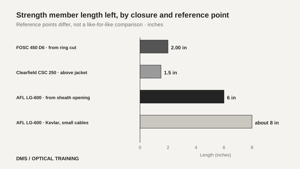 Strength member length left, by closure and reference pointView original
Scroll horizontally to view a wide table.
| Source | Strength member handling | Reference point for the length |
|---|---|---|
| FOSC 450 D6 (marked Tyco Electronics) | Rigid member left 2.00 in; center prong for a central member, outer two prongs for dual members | Cable ring cut |
| Clearfield CSC 250 | Left 1.5 in; cable about 2.0 in above the gel block top | Above the cable jacket |
| AFL LG-600 | Central member 6 in; Kevlar about 8 in on small cables | Sheath opening |
-
Read a length together with its reference point
-
Choose the position that matches the strength member count and cable diameter
-
The values in this table belong to each closure document and are not carried to another closure
How is the jacket gripped, and how tight?
FOSC 450 D6 says that when the strength member bracket is fitted into the smaller cable attachment part, the metal tab must sit in its slot and the attachment teeth must engage the cable jacket. The larger slotted part is then slid in and the hose clamp is tightened so that the teeth seat fully in the cable, but not so far that the clamp deforms. Large cables go in opposite slots of the bracket. For one marked cable type (AT&T/Lucent, high-density PE jacket) it recommends heating the jacket with a heat gun before assembly for maximum retention, and that advice is limited to that cable.
AFL LG-600 fixes the jacket to the frame with a hose clamp and uses two grommets (rubber parts that fill the hole the cable passes through) on each cable. The inner grommet goes about 4 in from the sheath opening. The grommets are described as self-adjusting for cables from 0.4 in to 1 in in diameter.
Read tightening values with care. In the pages reviewed, no torque value was found for the jacket clamp or the strength member bolt. The 15–20 in-lbs in the Clearfield manual belongs to the compression bolt that squeezes the gel block, not to the strength member bolt. For a part with no torque stated, use the document's own wording, such as teeth seated and no deformation, and do not borrow the torque of another part.
-
Check that the tab and slot of the strength member bracket line up
-
Tighten the hose clamp until the teeth seat but the clamp does not deform
-
Do not move a torque value from another part onto the jacket clamp
In what order is the seal made after retention?
In FOSC 450 D6 the order is cable retention and then gel end-piece. The gel end-piece goes 2 in behind the metal bracket, and each unused port gets a plug. The base is slid up, and the end-piece tail is turned to seal the cables and plugs, with a warning that turning the tail with a drill damages the end-piece. Cables under 0.35 in in diameter or flat drop cables need an extra step to build the diameter up to 0.35 in, and when several small cables share a port, gel must be applied between them.
Clearfield CSC 250 finishes the strength member and hose clamp, then tightens the compression bolt until the compression plate seats fully on the bottom of the endplate, at about 15–20 in-lbs. It notes that on large cables the teeth of the plate may not touch the endplate, but the gel block will seal if the proper torque is reached. Plugs for unused ports go in before the compression bolt is tightened.
The last check in both documents is 5 psi and soapy water. FOSC 450 D6 says to bleed all pressure through the valve afterward, and Clearfield warns that over-pressurizing can damage the closure or cause injury. If bubbles appear, Clearfield says to confirm the gel blocks are secured and to repeat the closing steps from the start.
-
Fit the sealing part after retention is done
-
Plug every unused port
-
Bleed the pressure after the test and do not over-pressurize
How are metallic strength members and shields handled?
A cable with metallic parts needs a bonding (electrically connecting the metal parts) and grounding check that is separate from retention. FOA says cables with metallic shielding or strength members must be properly bonded and grounded inside the closure and at each end. FOSC 450 D6 says that if a shield is present, a 1 in tab is made in the sheath, a bond wire is attached and two or three wraps of vinyl tape are applied, and the bond wire goes to the stranded wire from the closure bracket or to the ground feed-through lugs. AFL LG-600 says to take care that underlying layers of the cable are not damaged when shield bond connectors are installed, and to wrap the connectors with vinyl tape to protect the tubes from sharp edges.
Bonding method and grounding location depend on the closure and the cable construction. This lesson does not set an order for them and keeps them as a checklist item: for a cable with metallic parts, confirm that the bonding step in the closure instruction is finished.
-
Check first whether the cable has a metallic shield or strength member
-
Find the bonding step in the closure instruction and check it apart from retention
-
Protect the tubes around bond connectors
How would this be judged in a hypothetical case?
The situation below is assumed for training and is not a real site or measurement. Suppose an installer fits and tightens the strength member in the bracket but leaves the jacket hose clamp loose, then fits the gel end-piece and finishes a 5 psi test. There are no bubbles in the soapy water, so the test looks like a pass.
In both documents, however, pressurizing is used as a sealing check. The documents reviewed do not say that the test shows whether the cable is held, so reading a pass as confirmation of retention is not supported, which is DMS's interpretation. The order is therefore set as follows. Before sealing, look at whether the strength member is gripped by the bracket and whether the jacket clamp teeth have seated, and keep a photograph. Seal and test afterward, and write the test result in the sealing record.
-
Do not read a pressure test pass as confirmation of retention
-
Check retention by eye before sealing
-
Record the retention check and the seal test separately
What is recorded when the work ends?
The record lists the closure model and the version of the instruction, the cable diameter, the bracket position used, the strength member length left with its reference point, and the type of jacket retention part. A photograph of the retention and the pressure test result are kept separately. FOSC 450 D6 says to leave unused cable termination hardware in a bag inside the closure and to leave the remaining strain relief holders in their slots for later cables, so note where those parts are for whoever re-enters the closure.
The record also states what was not confirmed. This material is limited to manufacturer installation instructions and the FOA page, and no standard text was read. The tensile load each retention method withstands, the tightening torque of the jacket clamp or strength member bolt, and any test reproduced on real equipment were not confirmed. Record the values with the instruction of the closure in use as the source.
-
Write the instruction version, cable diameter and strength member length with its reference point
-
Keep the retention photograph and the seal test result separately
-
Record unconfirmed conditions as unconfirmed
Checklist
-
Did you check from which reference point the closure instruction measures strength member length?
-
Did you terminate both the jacket clamp and the strength member bracket and see by eye that the teeth seated?
-
Did you tighten the hose clamp without deforming it, without borrowing a torque value from another part?
-
Did you photograph retention before sealing and plug every unused port?
-
For a cable with a metallic shield or strength member, did you check the bonding step separately and record the pressure test result?
Review questions
1. Why should the strength member length not be memorized as one number?
Answer and explanation: The number and the reference point differ by closure. FOSC 450 D6 gives 2.00 in from the ring cut, Clearfield CSC 250 gives 1.5 in above the jacket, and AFL LG-600 gives 6 in from the sheath opening. Check the number and the reference point together in the instruction of the closure in use.
2. Why are cable retention and sealing checked separately?
Answer and explanation: All three instructions fit the retention parts and the sealing parts as separate parts. Retention is made by the jacket clamp and the strength member bracket, and sealing is done by the gel end-piece or the gel block with its compression bolt. Checking one does not count as checking the other.
3. Can a pass on the 5 psi pressure test be taken to mean the cable is held firmly?
Answer and explanation: No. In both documents pressurizing with soapy water is used as a seal test, and the documents reviewed do not say it shows whether the cable is held. Check the strength member termination and the seating of the jacket clamp by eye before sealing and record them separately.
Sources
-
Tyco Electronics: FOSC 450 D6 Installation Instruction · print code F408.09/06, marked 2003, copy hosted by a distributor
-
AFL: LG-600 Aerial Splice Closure Installation Instructions · P/N 41371-07 Revision 1, marked September 14, 2023
-
Clearfield: CraftSmart Splice Closure 250 Installation Manual · Manual 025150 REV A, marked December 2025
-
FOA: Fiber Optic Splice Closures · no date in the page body, marked 2023