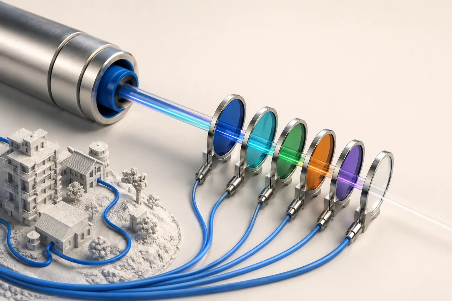
One Fiber, Several Systems
A PON that started as GPON often ends up carrying XGS-PON as well, plus an RF video overlay, plus monitoring. All of it on the same glass.
That works because each system is assigned its own wavelength, and passive filters separate them. Understanding the wavelength plan is what lets you predict which upgrades are possible on existing plant and which are not.
The Generations You Will Meet
표가 넓으면 좌우로 스크롤하여 확인하세요.
| System | Downstream | Upstream | Line rate |
|---|---|---|---|
| GPON | 1490 nm | 1310 nm | 2.5G down / 1.25G up |
| XG-PON1 | 1577 nm | 1270 nm | 10G down / 2.5G up |
| XGS-PON | 1577 nm | 1270 nm | 10G symmetric |
| RF video overlay | 1550 nm | — | broadcast |
Two observations matter more than the numbers.
GPON and XGS-PON occupy different windows in both directions. That is deliberate, and it is what makes coexistence possible — the subject of the next lesson.
The 1550 nm region is spoken for where video overlay exists. This is why an operator carrying RF video has less freedom in later upgrades, and why reflections matter more on those networks.
Why the Upstream Wavelengths Are Awkward
Downstream wavelengths are comfortably separated. Upstream is tighter: GPON at 1310 nm occupies a fairly wide band, and XGS-PON sits at 1270 nm just below it.
The practical consequence is that upstream filtering is harder than downstream filtering, and the components that combine the two generations have to be good. On plant where coexistence is planned, this is not a place to save money.
It also means the fiber's water peak region and its attenuation profile across 1260–1360 nm matter. This is one of the reasons G.652.D — with its low water peak — became the standard rather than older G.652 variants.
The Split Ratio Question Comes Back
As covered in the power budget lesson, split loss dominates the budget. Different PON generations specify different loss classes, and the class determines how much total loss the system tolerates.
Higher-rate systems are generally less tolerant, not more. A 1:64 split that works for GPON may not leave enough margin for a 10G system on the same plant, because the receiver sensitivity does not improve proportionally with the rate.
This is the single most common surprise during an upgrade project: the fiber is fine, the split is the problem. And splits are physical — changing them means touching plant.
What Determines Whether Your Plant Can Take the Next Generation
Four things, in order of how often they block an upgrade:
1. Total loss budget with the existing split. Measure it. Do not calculate it from the design, because as covered in the acceptance lesson, repairs have added splices since then.
2. Distance from OLT to furthest subscriber. Higher rates are more sensitive to dispersion over distance, and the differential distance limits discussed in the registration lesson still apply.
3. Connector return loss. Higher-rate systems are less forgiving of reflections. APC throughout matters more, not less, as rates increase.
4. Fiber type. G.652.D across the plant is fine. Older fiber with a high water peak may struggle in the upstream bands.
Notice that three of the four are things you measure, not things you look up. The as-built record tells you what was designed; only measurement tells you what you have.
The Practical Sequence Before an Upgrade
- Measure end-to-end loss at the wavelengths the new system will use, not just the ones currently in service. A link that is fine at 1490 may not be fine at 1577.
- Check reflectance on every connector in the path.
- Confirm the actual split ratio and architecture against the drawing. Two-stage splits added later are a common discrepancy.
- Establish the real distance, including slack.
- Compare against the loss class the new equipment requires.
Step 1 is skipped constantly, and it is the one that most often reveals the blocker.
What This Means for New Builds
If you are designing plant now, the wavelength plan gives you a straightforward instruction: design for the generation after the one you are deploying.
Concretely:
- Keep the split ratio conservative enough that a 10G class system will still close.
- Use APC connectors throughout.
- Use G.652.D or better, with G.657 where bends demand it.
- Leave the 3 dB of margin discussed in the power budget lesson, and document the remaining margin so the next engineer knows what is available.
None of these cost much at build time. All of them are expensive to retrofit.
Summary
- Each PON generation occupies its own downstream and upstream wavelengths, which is what allows several to share one fiber.
- Upstream separation (1310 vs 1270 nm) is tighter than downstream, so combining components must be good.
- Higher rates tolerate less loss, not more. The split ratio, not the fiber, is the usual upgrade blocker.
- Measure loss at the new system's wavelengths before planning an upgrade. Design records are not enough.
- On new builds, design for the next generation: conservative split, APC throughout, G.652.D, documented margin.