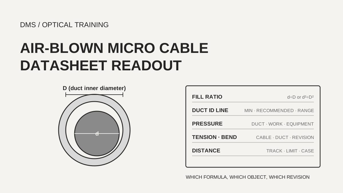
The fill ratio in air-blown micro cable documents is calculated with different formulas, so the same 65% is about 42% as an area ratio when it is a diameter ratio, and about 81% as a diameter ratio when it is an area ratio. Of the 17 documents read here, five print a formula: FOA and Dura-Line use a diameter ratio, Nexans and the STL micro cable guide use an area ratio, and the STL installation note prints both. The duct inner diameter line of a cable datasheet, the pressure, tension and bend lines of a duct document, and the installation tension and bend lines of a cable document describe different objects, so copy the line label and the document code with each value to keep them from being mixed in one plan.
Based on documents checked on November 22, 2026.
Learning objectives
-
Confirm for each document whether the fill ratio is a diameter ratio (d÷D) or an area ratio (d²÷D²), calculate both, and write which formula's limit was compared.
-
Write the duct inner diameter line of the cable datasheet next to the general fill ratio guidance, and do not replace one with the other.
-
Copy each pressure, tension and bend line with the object it belongs to (duct, cable or equipment) and the document revision.
How is the fill ratio of micro cable blowing calculated?
The fill ratio is calculated from the cable outside diameter d and the duct inside diameter D, but the documents mix a diameter ratio (d÷D×100) with an area ratio (d²÷D²×100). The FOA article on air blowing and the Dura-Line microduct datasheet use the diameter ratio, and the Nexans white paper and the STL micro cable guide use the squared ratio, that is, the area ratio. The STL installation note prints both formulas and gives 35–65% for the area ratio and 30–80% for the diameter ratio as the optimum ranges. The Belden installation guide says the cable diameter should be about 50% of the duct inner diameter without a formula, and the sentence sits in a discussion of large ducts such as 32/40 mm, so it was not carried over as a microduct limit.
The same number means different things under different formulas. An area ratio of 65% is about 80.6% as a diameter ratio, and a diameter ratio of 65% is about 42% as an area ratio (DMS conversion). FOA gives 50–70% (diameter ratio) as optimum and 80% as the maximum, and explains that below 50% the cable may buckle inside the duct. Dura-Line recommends 50–75%. Nexans writes an area ratio below 65% and adds that larger cables can be used but performance is affected. The STL micro cable guide says no greater than 60 to 70% as an area ratio and notes that cables have been jetted at higher ratios with higher air pressure. Converted, the upper limits cluster around 80% of diameter, while the lower limit splits between 50% (FOA) and about 59% (STL installation note, area 35%).
The basis of the limits also differs. FOA and Dura-Line print ranges without test conditions, and the STL micro cable guide says the value was determined empirically from actual jetting experience. The STL installation note also says a higher ratio helps distance in a straight route but may shorten it in a route with many bends. No document gives a limit per cable type. The fill ratio is therefore a first screen for candidates, and the final value should be copied from the duct inner diameter line of the datasheet of the cable itself (DMS interpretation).
Scroll horizontally to view a wide table.
| Document | Printed formula | Printed range | Converted to diameter ratio |
|---|---|---|---|
| FOA air blowing article | d÷D | optimum 50–70%, maximum 80% | as printed |
| Dura-Line microducts (DL.MDHDPE.8.22) | d÷D | recommended 50–75% | as printed |
| STL installation note (issued February 2015), formula b | d÷D | 30–80% (micro cable 1–9 mm) | as printed |
| STL installation note (issued February 2015), formula a | d²÷D² | 35–65% | about 59–81% |
| STL micro cable guide (issued March 2014, reissued December 2019) | d²÷D² | no greater than 60–70% | about 77.5–83.7% or less |
| Nexans microblown cable white paper (2021) | d²÷D² | below 65% | below about 80.6% |
| Belden installation guide (file name 202009) | no formula | cable diameter about 50% of inner diameter (large ducts) | excluded, large-duct text |
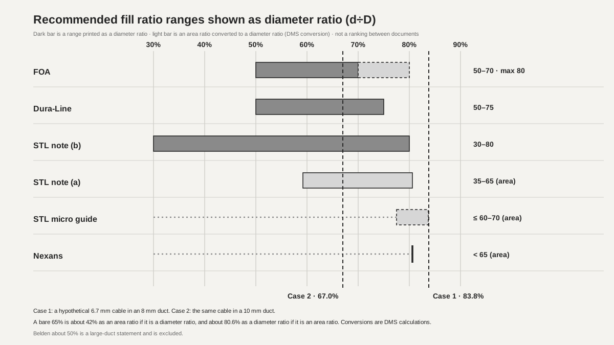 Bars of the recommended fill ratio ranges converted to diameter ratioView original
-
Dark bars are ranges printed as diameter ratios, and light bars are area ratios converted to diameter ratios. The dashed part of the FOA bar runs up to its 80% maximum
-
Documents with only an upper limit are marked at the upper limit. The vertical dashed lines are the diameter ratios of the hypothetical cases in this lesson
-
This is not a ranking between documents. Test conditions differ by document
Does the duct inner diameter line of a cable datasheet agree with the fill ratio limits?
The duct inner diameter line of a cable document carries different names (minimum inner diameter, recommended microtube diameter, a range of duct inner diameters, a pair of duct and cable outside diameter), and none of the documents prints a fill ratio calculation beside it. The Prysmian Sirocco product page prints a minimum microduct ID as a column, and the Hexatronic Viper datasheet prints pairs such as duct ID 8–10 mm with cable OD up to 6.7 mm. Optomer prints a recommended microtube diameter, and Xcom prints a range of microduct inner diameters. Dura-Line does the reverse and prints, in its duct document, the cable outside diameter range and fiber count for each duct size.
Calculating the values in the table with both formulas shows whether each line stays inside the limits of the previous section. The Prysmian 144-fiber cable (24 fibers per tube) has an outside diameter of 7.7 mm and a minimum duct ID of 10 mm, which is 77.0% as a diameter ratio and 59.3% as an area ratio, and the SiroccoHD 288-fiber cable (12x24) has 8.0 mm in a 10 mm duct, which is 80.0% and 64.0%. Hexatronic gives 2,000 m for its 144-fiber (6x24) 6.7 mm cable in ducts of 8–10 mm ID, but in an 8 mm duct the ratios are 83.8% and 70.1%, which exceeds the diameter ratio limits of 80% and 75% and the area ratio limit of 65% from the previous section, and also exceeds the 70% limit of the STL micro cable guide by 0.1 point. In a 10 mm duct the ratios are 67.0% and 44.9%. Because a minimum inner diameter printed by the manufacturer can exceed the upper limits of a general guide, do not use the guide to overrule or replace the datasheet line, and write both values side by side.
The Xcom GCYFY datasheet (V7.0, March 20, 2018) groups columns of different fiber counts into merged cells, so text extraction alone could not tell which column the cable outside diameter and the duct inner diameter range belong to. The page was opened as an image: the 144-, 192- and 216-fiber column has an outside diameter of 7.9 mm with a duct inner diameter of 10–14 mm, and the 576-fiber column has 13.4 mm with 16–20 mm. The document also prints its distance line once across all columns instead of per column. A table with merged cells should not be copied from extracted text; confirm the column range from the page image.
Scroll horizontally to view a wide table.
| Cable document | Cable OD mm | Duct inner diameter line printed | Diameter ratio % | Area ratio % |
|---|---|---|---|---|
| Hexatronic GNHL 144/T24 (6x24, +C edition) | 6.7 | duct ID 8–10 mm (at 8 mm) | 83.8 | 70.1 |
| Hexatronic GNHL 144/T24 (6x24, +C edition) | 6.7 | same line, at 10 mm | 67.0 | 44.9 |
| Prysmian Sirocco 12–72 fibers | 5.7 | minimum duct ID 8 mm | 71.3 | 50.8 |
| Prysmian Sirocco 96 fibers | 6.5 | minimum duct ID 10 mm | 65.0 | 42.3 |
| Prysmian Sirocco 144 fibers (24 per tube) | 7.7 | minimum duct ID 10 mm | 77.0 | 59.3 |
| Prysmian SiroccoHD 288 fibers (12x24) | 8.0 | minimum duct ID 10 mm | 80.0 | 64.0 |
| Prysmian SiroccoHD 864 fibers | 11.0 | minimum duct ID 14 mm | 78.6 | 61.7 |
| Optomer minicable 8.3 mm column | 8.3 | recommended microtube 12 mm | 69.2 | 47.8 |
| Xcom GCYFY 144, 192 and 216 fibers | 7.9 | microduct inside 10–14 mm (at 10 mm) | 79.0 | 62.4 |
| Dura-Line 12.7/10 duct | 5.0–7.5 (up to 144 fibers) | minimum ID 9.8 mm | 51.0–76.5 | 26.0–58.6 |
Are the pressure, tension and bend limits the same for every 12/10 microduct?
12/10 is only a designation meaning 12 mm outside and 10 mm inside diameter, and it does not fix any limit. The 12/10 lines of the four documents here give a minimum bend radius from 120 to 229 mm and a tension from 240 to 507 N. The Emtelle document and the older Optomer edition both print 240 N, 150 mm and 15 bar, but under different labels: Emtelle gives the maximum rated pressure at 20 °C, and Optomer gives the maximum recommended blowing pressure at 20 °C. The newer Optomer edition changes the same 12/10 to 465 N, 120 mm and a nominal installation pressure of up to 16 bar, and because neither edition prints a date, the documents alone cannot show which one is current. Dura-Line prints tension as safe working pull strength (SWPS, calculated at 80% of tensile or breaking strength) and splits the bend radius into supported and unsupported. The unsupported value is the guideline during installation and the supported value is a post-installation measurement. The Dura-Line 12/10 line has no pressure value.
Pressure lines also differ in the object they describe. A pressure in a duct document is what the duct can withstand, and a pressure in a work instruction is a setting during blowing. The Hexatronic installation instruction lists a compressor of up to 15 bar and 1,000 liters per minute or more, and says to start with no air in the duct, pushing with the motor only, and to add 1–2 bar when the speed drops. Nexans limits the duct check to 8 bar and lubrication to 4 bar and gives a starting speed of 40–60 m/min. FOA gives about 14 bar as the maximum for a general system of 6–20 mm cable in 20–60 mm duct, and Belden gives a minimum of 7 bar and a recommended 8.5 bar for 32/40 mm ducts. Prysmian says only that settings such as air pressure, flow and speed are set by the blowing equipment manufacturer and that the installer must confirm the equipment is approved, and it gives no numbers. Write first whether a pressure is a duct rating, a work setting or an equipment value (DMS interpretation).
Test methods appear in duct documents only as numbers. The Hexatronic microduct assembly 5/3.5 mm document lists IEC 60794-1-2 E-series methods such as crush E3, impact E4, bend E11A and kink E10, and puts the values in the model rows. The standard texts were not read, so only the numbers are copied.
Scroll horizontally to view a wide table.
| Document | Duct name | Minimum bend radius | Tension | Pressure line |
|---|---|---|---|---|
| Emtelle MHT2100 (Issue D, April 8, 2013) | 12/10 microduct, inner diameter 10.0 mm | 150 mm | maximum installation tension 240 N | maximum rated pressure at 20 °C 15 bar |
| Optomer microducts older edition (no date printed) | MIK-12-MR 12/10 | 150 mm | maximum pulling strength 240 N | maximum recommended blowing pressure at 20 °C 15 bar |
| Optomer microducts newer edition (no date printed) | thin wall 12/10 | 120 mm | maximum pulling strength 465 N | nominal installation pressure up to 16 bar |
| Dura-Line DL.MDHDPE.8.22 (code suggests August 2022) | 12/10 DI, minimum ID 9.9 mm | 5 in (127 mm) supported, 9 in (229 mm) unsupported | SWPS 114 lb (about 507 N, DMS conversion) | no line |
Which revision should the installation tension and bend limits of a cable be copied from?
The installation tension and bend lines of a cable document differ between documents even for one product family. For the 144-fiber lines (including the 6x24 cable with a 6.7 mm outside diameter) from Hexatronic, the permanent bend radius is 90 mm in the DIN VDE 0888 preliminary edition (Rev PC1 PRELIMINARY, no date printed) and 70 mm in the +C edition dated May 27, 2024. The crush value also differs, 2,200 N/100 mm against 2,000 N/100 mm. The installation tension is 1,600 N in both. The colour code (DIN against TIA 598) and the printed document differ, so the documents alone cannot show whether this is a revision difference of one product, and the document used and its revision should be written together.
Prysmian and Xcom give the bend limit as a multiple of the cable diameter. Sirocco is 20 times under load and 15 times without load, which for the 5.7 mm cable is 114 mm and 85.5 mm (DMS calculation), and the Prysmian installation procedure also states 15 times without load and 20 times with load unless otherwise specified. Xcom gives static 10D and dynamic 20D without defining the two words. For installation tension, Prysmian prints 694 N (156 lbf) for installation and 231 N (52 lbf) for operation on the 12–72 fiber cable, and Xcom prints a maximum tensile strength line of 200–1,200 N by construction plus a separate line of short term 1.0G and long term 0.3G (G is the cable weight per km written in N). The document does not explain how the two lines relate.
An installation tension line also does not directly limit the force on the cable during blowing. FOA explains that air spreads the force along the whole cable so the tension at any single point is much lower, and Hexatronic, STL, Belden and Nexans say to run a crash test, pushing the cable into a blocked duct, before the job to set the maximum force the machine may apply. None of the cable datasheets here gives a maximum pushing force as a number. Belden writes limits of 55 bar for loose tube cable under 15 mm diameter and 35 bar for cable under 12 mm but does not name the machine, so it reads as a machine setting rather than newtons (DMS interpretation).
Scroll horizontally to view a wide table.
| Document | Cable | Bend limit | Installation tension | Operating tension | Crush |
|---|---|---|---|---|---|
| Hexatronic Viper DIN VDE 0888 (Rev PC1 preliminary) | 144-fiber line (including 6x24 6.7 mm) | 90 mm (permanent, multiple turns) | 1,600 N | 75 N | 2,200 N/100 mm |
| Hexatronic High Performance Micro Cable (+C edition, May 27, 2024) | 144 fibers 6x24, outside diameter 6.7 mm | 70 mm | 1,600 N | no line | 2,000 N/100 mm, impact 5 J |
| Prysmian Sirocco product page | 12–72 fibers, outside diameter 5.7 mm | 20 times under load (114 mm), 15 times without load (85.5 mm) | 694 N (156 lbf) | 231 N (52 lbf) | 1,000 N/100 mm |
| Xcom GCYFY V7.0 (March 20, 2018) | per outside diameter column | static 10D, dynamic 20D | short term 1.0G, 200–1,200 N by construction | long term 0.3G | short term 500, long term 150 N/100 mm |
| Optomer minicable (no date printed) | 6.5 mm column | 100 mm | maximum tensile 2,000 N | no line | 1,500 N |
Under what conditions is a blowing distance printed in a datasheet?
Blowing distances carry values of different kinds under the same words. The Hexatronic cable datasheet gives values verified on its own test track according to IEC 60794: 2,000 m for duct ID 8–10 mm with cable OD up to 6.7 mm, 2,000 m for ID 12 mm with OD up to 8.0 mm, 2,000 m for ID 15–16 mm with OD under 11 mm, and 1,500 m for OD 11–12 mm, and it adds that actual performance can differ with route, environment and equipment. The Prysmian installation procedure recommends a maximum of 5,000 ft (about 1,524 m) for one run because route variables are large, says to use a mid-assist or a figure-8 method beyond that, and notes that distances above 7,000 ft (about 2,134 m) have been blown. The Prysmian Sirocco product page says up to 6 miles (about 9.7 km) was demonstrated cascaded and does not explain how the sections were connected.
General guides give ranges or cases. Nexans says experienced installers at its seminars reached up to 3,000 m with traditional cable in traditional ducts and that 500–600 m is enough for the last part of an access network. Belden says 1,000 to 2,000 m is a typical blowing length, and STL says microduct cable can be installed in continuous lengths of more than 1,000 m depending on the route. FOA gives about 3–4 km continuous and 80–120 m/min for a general system of 6–20 mm cable in 20–60 mm duct. The 2 km from Optomer is for a fibre unit, not a cable, with a 3.5 mm duct, 10 bar and 2 m³/min. Environmental conditions differ too. Hexatronic gives a cable temperature of −15 to +40 °C for blowing and FOA gives about −10 to 49 °C, and FOA explains that high altitude lowers air density and reduces distance.
A distance plan has to separate the distance reached in one run from the distance reached by chaining runs with mid-assists. The Hexatronic installation instruction treats its example route of 4,400 m in total as impossible in one run, starts from an intermediate point and blows in two directions, and extends length by coiling (the Figarino storage device or a figure-8) and by placing equipment in tandem. The statement in the Emtelle catalogue (2023) that an inner liner improves blowing speed and distance by up to 50% is a manufacturer claim, and no basis conditions are printed with it.
Scroll horizontally to view a wide table.
| Document | Distance printed | Conditions the document attaches |
|---|---|---|
| Hexatronic High Performance Micro Cable | 2,000 m (ID 8–10 mm with OD up to 6.7 mm, and others), 1,500 m (ID 15–16 mm with OD 11–12 mm) | own test track, IEC 60794, actual performance may differ |
| Prysmian installation procedure (file name 09-18) | 5,000 ft (about 1,524 m) recommended per run, a case above 7,000 ft (about 2,134 m) | route variables, speed 100–300 ft/min (about 30–91 m/min) |
| Prysmian Sirocco product page | 6 miles (about 9.7 km) demonstrated cascaded | connection method not stated |
| Xcom GCYFY V7.0 | 1,200 m or more | test field 2x50 m (one line across all columns) |
| Nexans white paper (2021) | case of 3,000 m with traditional cable, 500–600 m in the access network | duct installation, temperature, installer experience |
| Belden and STL | typical 1,000–2,000 m and continuous lengths above 1,000 m | equipment supplier advice and duct route |
| Optomer | 2 km | fibre unit, 3.5 mm duct, 10 bar, 2 m³/min |
| FOA | about 3–4 km continuous | system of 6–20 mm cable in 20–60 mm duct |
What happens when field conditions are put against the datasheets?
The cases here are hypothetical teaching calculations and are not tests of a real site or product. Case one is a Hexatronic 144-fiber cable of 6.7 mm outside diameter in an 8 mm inner diameter duct. The duct inner diameter line of the cable datasheet allows it, but the diameter ratio of 83.8% and the area ratio of 70.1% exceed every fill ratio limit read here. Do not pick one side; write both values in the same plan, together with the condition that the 2,000 m line is a test-track value. Case two puts the same cable in a 10 mm duct, which gives 67.0% and 44.9% and falls inside the ranges of FOA, Dura-Line, Nexans and STL. Case three puts the Prysmian Sirocco 144-fiber cable (24 fibers per tube) in a duct of 10 mm minimum inner diameter. The 77.0% and 59.3% are within the FOA maximum of 80% and the area ratios of Nexans and STL, but above the FOA optimum of 50–70% and above the Dura-Line recommended upper limit of 75%.
The limits of this material are clear as well. The texts of the IEC 60794-1-2 test methods, the IEC 60794-5 series (microduct cabling) and ITU-T L.156 were not read, and for ITU-T L.156 only a search result summary was seen. Corning AEN096 and AEN154 could not be read because access was blocked, and although a diameter ratio formula and a 50–80% range appeared in a search result excerpt, they were not counted as evidence. The setting tables of blowing equipment makers and lubricant instructions were not read either. Whether each document is the current revision and matches the model sold today was not confirmed, and every value is a value published by a manufacturer or an association, not an independent test.
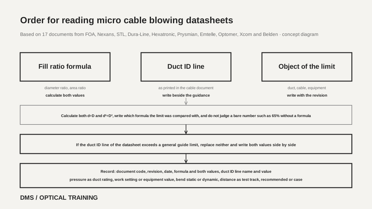 Order for reading micro cable blowing datasheetsView original
-
Confirm the formula first and calculate both the diameter ratio and the area ratio
-
Write the duct inner diameter line of the cable datasheet beside the general guidance and do not replace one with the other
-
Write pressure, tension and bend with the object (duct, cable or equipment) and the revision
Scroll horizontally to view a wide table.
| Hypothetical condition | Fill ratio | Relation to the guidance | Cannot be judged or no line |
|---|---|---|---|
| 144 fibers 6.7 mm in an 8 mm duct | 83.8%, 70.1% | datasheet line allows it, every limit read here is exceeded | distance line is a test-track value |
| same cable in a 10 mm duct | 67.0%, 44.9% | inside FOA, Dura-Line, Nexans and STL ranges | no pressure or pushing force line |
| Sirocco 144 fibers 7.7 mm in a 10 mm duct | 77.0%, 59.3% | FOA maximum 80% and area ratios inside, Dura-Line 75% exceeded | settings are in the equipment document |
Checklist
-
Did you confirm the formula (diameter ratio or area ratio) in each document, calculate both values and write which limit was compared?
-
Did you copy the name and value of the duct inner diameter line of the cable datasheet (minimum, recommended, range, pair) as printed, and write it beside the general guidance?
-
Did you write whether a pressure line is a duct rating, a work setting or an equipment value?
-
Did you write the document code and revision, static or dynamic, and installation or operation with each bend and tension line?
-
Did you write whether a distance line is a test-track value, a recommended limit or a field case, together with the environmental conditions?
Review questions
1. A guide says only that the fill ratio should be 65% or less. May a cable of 6.7 mm outside diameter go into a duct of 10 mm inner diameter?
Answer and explanation: Do not decide when the formula is not printed. As a diameter ratio, 6.7÷10 is 67% and exceeds 65%, and as an area ratio it is 44.9% and is within 65%. Write both values and compare after confirming the formula of the guide. If the cable datasheet has a duct inner diameter line, write that line as well.
2. A cable datasheet gives 2,000 m for duct ID 8–10 mm with OD up to 6.7 mm, and a general guide gives a diameter ratio upper limit of 80%. Which one does a plan with a 6.7 mm cable in an 8 mm duct follow?
Answer and explanation: Do not replace one with the other; write both values. 6.7÷8 is 83.8%, which is above the upper limit of the general guide, and the datasheet line is a value confirmed on the manufacturer's test track, with a note that actual performance may differ. Write both values and the document codes in the plan and decide after confirming with a larger duct or a test report where possible (DMS interpretation).
3. One document gives the maximum installation tension of a 12/10 microduct as 240 N and another gives 465 N. Which value goes into the work standard?
Answer and explanation: Use only the value in the document of the manufacturer and model of the duct to be used. 12/10 is only a designation, so a value from another manufacturer or another revision must not be carried over. Write the document code and the revision date together, and where no date is printed write that no date is printed and check separately whether the document is current.
Sources
-
FOA: Cable and Microcable Installation by Air Blowing (2026) · pages 1 to 2
-
Nexans: Microblown Cable Installation White Paper (15/2021) · pages 2 to 7
-
STL: Installation of Optical Fiber Cable by Blowing/Jetting (issued February 2015) · pages 3 to 4
-
STL: Micro Cables, Application (issued March 2014, reissued December 2019)
-
Dura-Line: Microducts HDPE (DL.MDHDPE.8.22) · pages 1 to 3
-
Belden: Optical Fiber Cable Installation Guideline (file name 202009) · pages 8 to 9
-
Hexatronic: High Performance Micro Cable (28701-TOL4019022+C, May 27, 2024) · pages 1 to 7
-
Hexatronic: Microduct Cable, The Viper Series, DIN VDE 0888 (Rev PC1 PRELIMINARY, no date printed) · pages 1 to 3
-
Hexatronic: Installation of Micro Cables (1531-TOL 401 90 Rev B) · pages 4 to 15
-
Hexatronic: Microduct Assembly 5/3.5 mm (28701-N-MPB30244+M, November 10, 2025) · pages 2 and 5
-
Prysmian: Microduct Fiber Optic Cable Installation (file name 09-18) · pages 1 to 2
-
Emtelle: fibreflow 12/10 microduct product specification MHT2100 (Issue D, April 8, 2013) · page 1
-
Emtelle: Catalogue 2023 · EM-Liner page
-
Optomer: Microducts, older edition (no date printed) · page 3
-
Optomer: Microducts, newer edition (no date printed) · pages 2 to 4
-
Xcom: GCYFY micro duct cable specification (V7.0, March 20, 2018) · pages 2 and 5