How RF Signals Travel over Optical Fiber
An acceptable received optical power does not, by itself, prove that an RF signal has arrived with acceptable quality. Light can reach the receiver while noise, nonlinearity, frequency response or dispersion degrades the recovered electrical signal. Understanding RF-over-Fiber (RFoF) therefore requires treating the fiber plant and the RF link as related but distinct parts of the system.
This lecture is intended for fiber-network and optical-product engineers, RF and satellite-communications staff, and technical sales teams. The topic came from a user-supplied LinkedIn post; the explanations were independently developed against manufacturer documentation, technical literature and interface specifications. The original attachment has not been reproduced. Although the post title refers to a PDF guide, a separate downloadable document was not available for full review in the inspected post, so this lecture does not claim to summarize that entire PDF.
Lecture information and learning objectives
The suggested delivery time is 60 minutes. Learners should already understand basic fiber construction and the distinction between dB and dBm. Delivery consists of explanations, diagram walkthroughs and instructor notes; there are no worked examples, exercises or quizzes. Equipment specifications and agreed test conditions take precedence over this general teaching material, which is not a product-performance guarantee or an acceptance specification.
By the end of the lecture, learners should be able to explain the path from RF input through optical conversion and transport to RF recovery, distinguish analog RFoF from digital fronthaul, and interpret gain, noise figure, linearity and dynamic range. They should also understand how optical loss, reflections, dispersion, remote power and environmental conditions relate to RF measurement and acceptance evidence.
Scroll horizontally to view a wide table.
| Lecture block | Time | Main explanation |
|---|---|---|
| Purpose and transport methods | 8 minutes | What is carried and how RFoF differs from other optical transport |
| Signal path and components | 12 minutes | Electrical-to-optical conversion and RF recovery |
| RF link performance | 15 minutes | Gain, noise, compression, intermodulation and dynamic range |
| Fiber plant and system design | 12 minutes | Loss, dispersion, WDM, direction, power and environment |
| Measurement, acceptance and closing | 13 minutes | Separating optical-plant evidence from RF-performance evidence |
These timings are an instructor delivery plan, not a record of a timed classroom session.
1. The transport problem RFoF addresses
Radio-frequency signals are electrical signals used in wireless transmission and reception. When signal-processing equipment and an antenna are separated, a transport path must connect them. With coaxial cable, attenuation depends on the cable construction, length and operating frequency; diameter, weight, grounding and installation constraints also matter.
RFoF places information from that electrical signal onto an optical signal, transports the light through fiber and recovers an electrical signal at the receiving end. The fiber medium is resistant to electromagnetic interference and does not itself create a conductive RF signal path. This can make it useful for antenna remoting and inter-facility RF transport. It does not mean that metallic cable strength members, equipment housings or power conductors are electrically isolated.
Long reach and broad operating bandwidth must not be presented as zero loss or zero noise. Optical transmitters and receivers impose their own limits, while increasing fiber length adds optical attenuation, dispersion and environmental considerations. Reach and operating frequency must therefore be verified for the complete equipment-and-fiber configuration rather than inferred from fiber alone.
Instructor note: Establish the distinction between fiber as a transmission medium and RFoF as a link containing conversion equipment. Do not extend the medium's resistance to EMI into a claim that the complete RF system is lossless or noiseless.
2. Analog RFoF and digital fronthaul are different transport methods
Analog RFoF maps continuous changes in the RF signal onto changes in an optical signal and recovers the RF content through optical detection. In a conventional intensity-modulation/direct-detection (IM-DD) link, the source or optical modulator varies the intensity of the light, and the photodetector converts received optical power into current. This is a useful teaching reference architecture, not a claim that every RFoF product uses the same modulation scheme.
Digital transport carries sampled signal information or processing results according to the chosen functional split. Receiving equipment interprets the digital data rather than simply detecting an analog RF waveform from optical intensity. The eCPRI specification supports packet transport, including Ethernet and IP transport, and includes IQ data alongside other bit sequences and control-message types. IQ describes two orthogonal components used to represent signal amplitude and phase; it is not the only information eCPRI can carry.
Scroll horizontally to view a wide table.
| Aspect | Analog RFoF | Digital fronthaul |
|---|---|---|
| Form of the transported information | Continuous RF variation represented in an optical signal | Digital data and messages appropriate to a functional split |
| Important quality measures | RF gain, noise figure, linearity, dynamic range and phase | Capacity, latency, delay variation, synchronization and protocol compatibility |
| Role of optical-plant tests | Necessary, but insufficient to establish RF quality | Necessary, but insufficient to establish service, synchronization or protocol performance |
| Equipment checks | Source, modulator, detector and RF-port conditions | Functional split and supported interface specifications |
Neither method is universally superior. The signal to be transported, processing architecture, distance, bandwidth and operating model determine which approach is appropriate. The useful distinction is what the equipment at each end processes, not merely whether both arrangements use fiber.
3. From RF input to recovered RF output
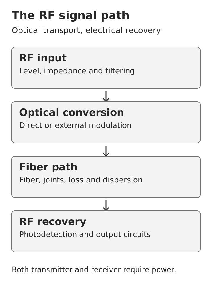 RF input, optical conversion, fiber transport, photodetection and RF output, with power required at both endsView original
At the input, the RF signal passes through the applicable matching, filtering and level-conditioning circuits before reaching optical conversion. Incorrect impedance or excessive input can cause reflection, compression or distortion before any light enters the transmission fiber. RF input conditions therefore belong in the same design review as the fiber route.
The transmitter directly modulates a light source or uses an external optical modulator. The optical signal then passes through connectors, splices and fiber to the receiver. The photodetector generates RF current from the received optical variation, and the output circuits deliver a usable electrical signal. Output level, output impedance and the next device's permitted input are part of the complete link.
The diagram describes one direction of transport. It is a functional diagram, not a product circuit schematic or a physical equipment drawing. A reverse path requires an additional path or a supported bidirectional arrangement; connecting a single strand does not automatically establish two-way RF transport.
Instructor note: Follow the signal through the RF port, conversion equipment, passive fiber plant and receiver. Distinguish light inside the fiber from electrical signals at the RF input and output ports.
4. Direct modulation and external modulation
Direct modulation varies the laser's drive conditions with the RF signal so that the optical output carries the information. It can provide a relatively compact architecture, but the laser's frequency response, noise, nonlinearity and operating conditions affect performance. A quoted maximum response bandwidth may be wider than the band over which useful low-distortion transport is available.
External modulation uses a separate optical modulator after the light source. Architectures using a Mach–Zehnder modulator must manage the operating bias point as well as optical input and RF drive conditions. The label “external modulation” does not itself guarantee low noise or high linearity; bias stability, photodetection and amplification still contribute to link performance.
Teach the architectures in terms of where performance is constrained rather than declaring an overall winner. If the product documentation does not specify modulation method, wavelength, optical power, input range or linearity conditions, leave those items unresolved instead of supplying an assumed circuit architecture.
5. Essential and optional components
The transmitter, receiver and connecting optical path are the basic transport elements. An antenna receives or radiates wireless signals but is not a mandatory component in every inter-facility RF connection. Amplifiers, switches, splitters and WDM devices are added according to the required architecture. A list of possible components should not be taught as a compulsory bill of materials for every RFoF system.
An RF preamplifier can reduce the importance of downstream noise for a weak signal, but it may also reduce the available headroom for strong input signals. A postamplifier can restore output level without restoring signal-to-noise ratio or removing distortion already created upstream. Gain, noise figure and input headroom must therefore be considered together when adding amplification.
An optical splitter divides received light among paths and introduces optical loss. An RF splitter divides electrical signals and has different port and impedance conditions. Mark the RF and optical domains separately in the architecture so that similarly named components do not cause their loss budgets or interface conditions to be confused.
6. RF frequency and optical wavelength are different coordinates
RF-port frequencies are normally specified in MHz or GHz, whereas the optical carrier's central wavelength is commonly specified in nm. Optical frequency and wavelength are related physical quantities, but the optical carrier and the transported RF carrier occupy different frequency domains. The name of an RF band is not a specification of the optical wavelength.
L, S, C, X, Ku and Ka are RF-band designations; the applicable naming scheme and the equipment's actual operating range must still be checked. In particular, RF C-band and the optical communications C-band refer to different frequency or wavelength regions despite sharing a name. A band designation alone does not establish satellite, GPS or cellular suitability, or equipment compatibility.
A procurement specification should identify the RF operating-frequency limits, occupied signal bandwidth, optical wavelength and permitted optical power as separate entries. Compatible optical wavelengths do not establish compatibility of RF bandwidth, input levels or linearity.
7. Link gain and frequency response
RF link gain is the ratio of RF output power to RF input power. In decibel form it is the difference between the two power levels. A negative gain is not automatically a fault: it must be evaluated against the expected link specification, installation conditions and required downstream output level.
Relationship: RF link gain in dB = RF output power in dBm − RF input power in dBm
Frequency response describes how gain changes across the operating band. Gain flatness describes the variation within that band, but manufacturers may specify it as a peak-to-peak difference or a deviation from a reference. Verify the definition rather than comparing unlike flatness figures. A valid result at one frequency does not rule out reduced response or a deep notch elsewhere in the required band.
Applications that depend on phase or timing relationships also require phase-response or group-delay review. Group delay is related to the rate of phase change with frequency, and its variation can affect complex waveforms or time alignment. Equal fiber lengths do not prove equal phase or delay behavior once conversion equipment and other components are included.
8. Noise figure and signal-to-noise ratio
Signal-to-noise ratio compares the wanted signal with noise. Noise figure describes how much the link degrades that ratio. A large output signal is not necessarily a clean signal if the noise has increased with it, so gain and noise figure must be taught as separate measures.
Relationship: Noise figure in dB = input SNR in dB − output SNR in dB
Thermal noise from electrical circuits, photodetection shot noise and laser relative-intensity noise can contribute to optical-link performance. Their relative importance depends on received optical power, modulation, detectors, amplifiers and operating frequency. Do not assign one noise mechanism as the dominant mechanism for all products and conditions.
Measured noise power depends on measurement bandwidth. Changing a spectrum analyzer's resolution bandwidth changes the observed noise floor and must not automatically be interpreted as a change in the device. Record frequency, temperature, fiber length, optical conditions, reference planes and measurement bandwidth when assessing or comparing noise performance.
9. Linearity, compression and intermodulation
Within a linear operating region, output changes proportionally with input. At higher levels, limitations in the laser, modulator, photodetector or RF amplifier cause departure from that relationship. The 1 dB compression point, P1dB, is the operating point at which gain is 1 dB below the small-signal gain. Identify whether a specification refers to input or output power.
P1dB is not the damage threshold and is not automatically the recommended continuous operating level. “No damage” does not mean “low distortion.” Signal peaks and the combined power of multiple carriers must be considered when setting operating headroom, with the required margin determined by the service and equipment conditions.
When multiple frequency components pass through a nonlinear circuit, intermodulation components can appear that were not present at the input. Third-order products can fall close to wanted signals and become difficult to separate. The third-order intercept point, IP3, is obtained by extrapolating measured linear trends; it is not a power at which the equipment can necessarily operate.
Instructor note: “A signal is present,” “the equipment is not damaged” and “the signal has low distortion” are different judgments. Do not collapse compression, damage and intermodulation specifications into a single maximum-input number.
10. SFDR describes usable range between noise and distortion
Spurious-free dynamic range, SFDR, describes the range between the lower limit set by noise and an upper limit at which distortion products reach the noise floor. Third-order-intermodulation-limited SFDR is common in RFoF documentation, but its definition, units and measurement bandwidth must accompany the value.
For a third-order-limited link with the applicable white-noise conditions, dynamic range over noise bandwidth B follows the relationship below. B is the noise bandwidth in Hz, not the RF band-edge frequency.
Relationship: SFDR₃(B) = SFDR₃(1 Hz) − (2/3) × 10 log₁₀(B / 1 Hz)
The 2/3 coefficient follows from the different power slopes: fundamental signal power is proportional to input power, while third-order distortion power is proportional to its cube. As a wider bandwidth raises the noise floor, the lower signal limit and the upper distortion limit move at different rates, producing this reduction in usable range.
The 1 Hz-normalized figure is commonly expressed as dB·Hz^(2/3), while the dynamic range over a specified bandwidth is expressed in dB. Product literature may use an alternative typographic convention such as dB/Hz^(2/3); check the underlying definition. Do not apply this conversion without qualification to ADC SFDR in dBc or to second-order-limited dynamic range. Increasing bandwidth accumulates more noise, so a normalized figure is not the usable range of every service bandwidth.
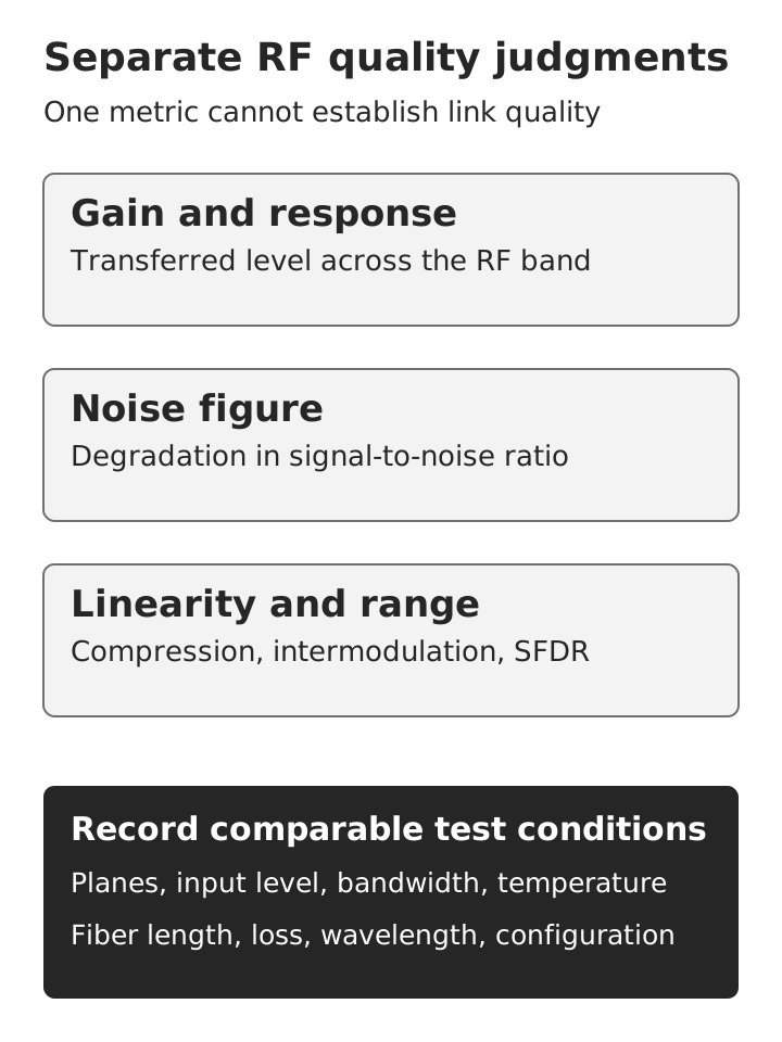 Gain, noise and linearity as separate RF-link judgments, supported by common test conditionsView original
Gain, noise figure, compression and SFDR are connected, but none replaces the others. Reporting gain alone can hide noise or distortion; reporting normalized SFDR without bandwidth can exaggerate the range available to the service.
11. Optical loss budget and recovered RF level
The optical loss budget includes fiber attenuation and losses from connectors, splices, optical splitters, WDM devices and other components. Received optical power is transmitted optical power minus total path loss. It must remain within the receiver's permitted range, including its maximum input; excessive optical power can be a problem as well as insufficient power. Reserve operating margin for the applicable temperature, aging, repair and measurement uncertainties.
Relationship: Received optical power in dBm = transmitted optical power in dBm − total optical-path loss in dB
Optical loss affects recovered RF level because the RF photocurrent is related to received optical power. In a simple IM-DD model with constant modulation depth, linear detection and output stages, and an unchanged load, RF power is proportional to the square of received optical power. Under those assumptions, the RF-power change in dB is twice the optical-power change in dB.
This relationship is not a universal product rule. Automatic gain control, internal amplification, saturation and dispersion-induced fading can alter the result. A change in RF output power also does not establish an equal change in SNR because the noise mechanisms may change differently. Use the manufacturer's gain-versus-optical-loss data and the actual measurement conditions.
A PON power budget should not simply be transferred to an RFoF design. Digital receivers operating through large passive splits and analog RF links with noise and linearity requirements have different limitations. Reusing available fiber still requires a new review of its route, components, wavelengths and optical loss.
12. Reflections and chromatic dispersion affect quality differently
Reflection at connectors or other interfaces is different from insertion loss. Light returning toward the source can affect noise and stability. Follow the equipment manufacturer's connector requirements, including APC where specified; do not directly mate APC and UPC interfaces. Match equipment ports, adapters and patch cords. Optical reflection and RF-port return loss are separate measurements.
Chromatic dispersion causes different optical wavelengths to experience different propagation delays. In optical-double-sideband/direct-detection architectures, dispersion-induced phase differences can affect the combination of RF contributions at detection and create frequency-dependent fading. This is different from uniform attenuation across the band. It depends on frequency, length, wavelength, modulation architecture and dispersion management, and should not be described as a universal monotonic loss mechanism.
A normal optical-power reading can coexist with a notch in the RF response. Higher RF frequencies or longer optical routes therefore require attention to frequency-response behavior, not optical loss alone. Wavelength selection must consider equipment and dispersion conditions rather than only the lowest fiber attenuation.
13. WDM and bidirectional transport
Wavelength-division multiplexing combines and separates optical wavelength channels on a shared fiber. Combining multiple RF carriers electrically before carrying them on one optical channel is a different operation. Multiple RF carriers do not automatically require WDM, and multiple optical wavelengths do not automatically eliminate RF noise, interference or nonlinearity.
A WDM design must include insertion loss, channel isolation, reflection, direction and temperature behavior as well as wavelength compatibility. Optical-grid spacing expressed in GHz is not the RF input bandwidth. Label optical channels and RF bands explicitly to avoid mixing the two domains.
Bidirectional transport can use separate fibers or supported wavelength-separated transmitter-and-receiver arrangements. Confirm RF frequency range, input level, optical output and receiver conditions for each direction independently. Standard Ethernet optical modules should not be treated as substitutes for analog RFoF conversion equipment.
14. Cable, splice closures and remote power
Select fiber type according to transmitter and receiver requirements, then assess the complete cable for its installation environment, tensile and bend limits, water protection, fire requirements and maintenance needs. Underground, aerial and underwater are deployment classifications, not evidence of RFoF reach, bandwidth or dynamic range. Performance of long-haul digital submarine transmission cannot be attributed to an analog RFoF link without appropriate evidence.
At a splice closure, cable entry, mechanical retention, splice protection, slack routing and bend control affect optical loss and long-term stability. A low initial splice loss is insufficient if closing the housing introduces pressure or later re-entry pulls the fibers. Routing, sealing and re-entry must follow the product instructions rather than a generalized closure layout.
The fiber itself does not supply operating power to remote equipment. Power-over-fiber arrangements exist, but are not assumed features of an ordinary RFoF system. Design voltage, consumption, grounding, surge protection and thermal management for remote transmitters, receivers and RF amplifiers. Resistance of the fiber to EMI does not remove the need to protect exposed electrical ports, supplies and housings.
15. Reading a specification under comparable conditions
A product comparison needs more than operating-frequency limits and maximum reach. Distinguish guaranteed limits from typical values, and identify the temperature, test-fiber length, optical loss, RF input level and measurement bandwidth used for each figure. Results obtained with a short patch cord must not be represented as guarantees for a long installed route.
Scroll horizontally to view a wide table.
| Specification group | Read together | Interpretation requirement |
|---|---|---|
| RF interface | Frequency range, impedance, connector and input/output levels | Entire operating band and downstream compatibility |
| Amplitude and timing | Gain, flatness, phase and group delay | Temperature and optical-path conditions |
| Noise and linearity | NF, P1dB, IP3 and SFDR | Reference planes, definitions and bandwidth |
| Optical interface | Wavelength, launch power, receiver range, fiber and connector | Maximum input, reflection and WDM compatibility |
| Environment and operation | Power, consumption, temperature, enclosure and monitoring | Guaranteed installation conditions and protection |
| Test conditions | Planes, fiber length/loss, frequency, temperature and instrument settings | Compare like conditions rather than isolated numbers |
Typical values can describe expected behavior without guaranteeing the worst case for every delivered unit. Establish acceptance against agreed requirements for the actual use conditions. Where a requirement lacks a measurement method or permitted range, resolve that gap before treating it as an enforceable acceptance criterion.
16. Separate optical-plant tests from RF-link tests
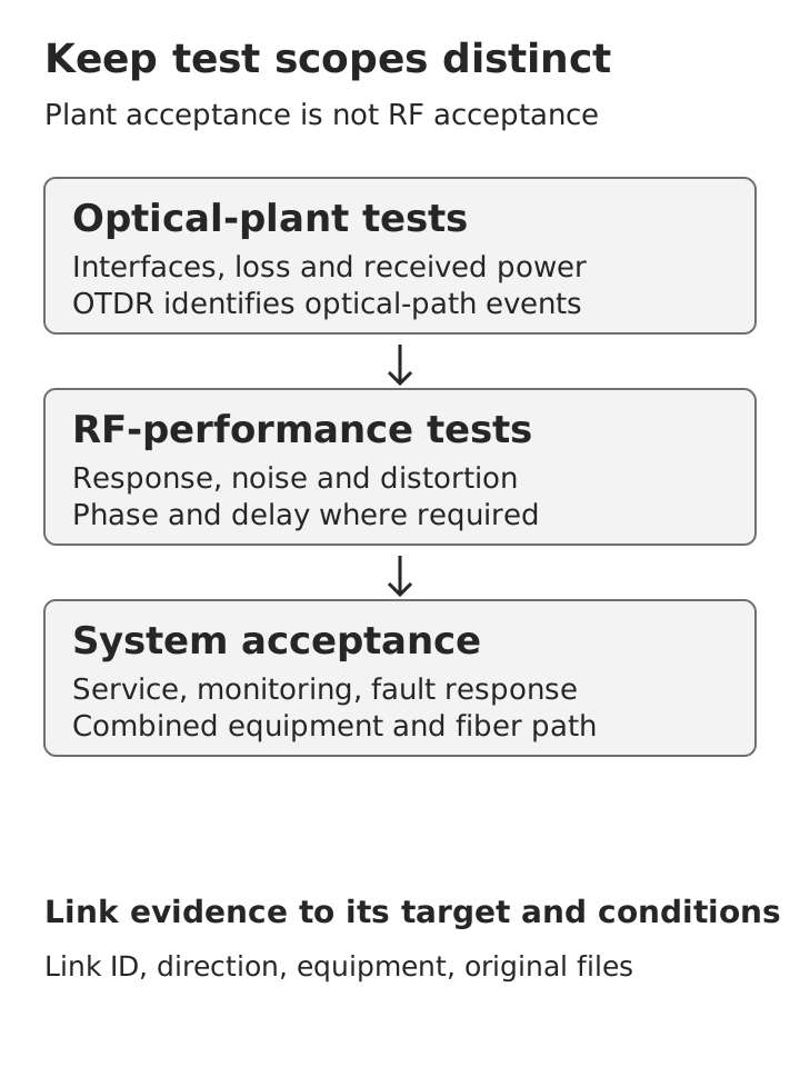 Separate optical-plant and RF-link tests, followed by system acceptance and traceable recordsView original
Optical-plant verification addresses connector cleanliness and mating, continuity, insertion loss at the relevant operating wavelength and received optical power. OTDR testing helps identify event locations and loss or reflection characteristics, but has a different purpose from optical-power or insertion-loss testing. It does not directly measure RF noise figure, intermodulation or frequency response.
RF-link verification uses defined input and output reference planes and load conditions to assess gain and frequency response, with noise figure, compression, intermodulation, phase or group delay measured where required. A vector network analyzer, signal generator and spectrum analyzer support different measurements; naming one instrument does not establish that all link parameters were verified. Instrument distortion, noise, level limits and cable calibration can affect the result.
System acceptance evaluates the combined equipment and fiber path against the service's quality, monitoring and fault-response requirements. Optical-plant acceptance, RF-performance acceptance and service acceptance are related but separate judgments. A healthy status indicator is not evidence that all three have been completed.
Instructor note: An OTDR trace supports a statement about the optical route. A spectrum or frequency-response result supports a statement about RF performance. Keep the evidence within the scope of the measurement that produced it.
17. Troubleshooting order and traceable records
Start by identifying the direction and ports, then verify power, alarms, configuration and RF input conditions before separating optical-path checks from RF-performance checks. Opening a closure first when a device is unpowered or a direction is incorrect introduces unnecessary intervention and possible additional loss.
If received optical power or path loss is outside the permitted range, check connector surfaces, patch cords, mating types, bends and the optical route. If the plant meets its requirements but RF quality is poor, investigate input level, matching, frequency response, noise, compression, dispersion and equipment conditions. A symptom is not a confirmed cause. Change one controlled item at a time and compare results under the same conditions; do not disable protective grounding or other safety measures to obtain a result.
Acceptance and maintenance records should link the route ID and direction to equipment model, serial number, firmware and configuration; optical path, wavelength and received power; RF reference planes, frequency, input level and bandwidth; temperature, supply conditions and original measurement files. Values without targets or conditions cannot be reliably compared later. Preserve acceptance limits, judgments and unresolved items with the measurements.
Never look directly into an optical port or fiber end. Connection, cleaning, inspection and instrument use must follow laser-safety procedures and equipment requirements for power and maximum input. Safe work and damage limits remain mandatory even when a lesson focuses on performance.
Closing explanation
RFoF carries RF information optically and restores it electrically, with performance determined by conversion equipment, RF interfaces, fiber plant, power and operating conditions. Analog transport requires gain, noise, linearity and dynamic range to be understood together; it should not be evaluated as though it were a digital fronthaul interface with the same capacity, synchronization and protocol criteria.
Loss, reflection and dispersion affect RF quality in different ways, while WDM combines optical wavelength channels rather than RF frequencies. The final distinction for the class is between light reaching the receiver and the required RF quality being established. Each judgment needs measurements made and recorded under the relevant conditions.
Sources and review limits
Reviewed on October 13, 2026. Older literature and interface versions support principles and definitions, not claims about the latest product performance or market size. Source diagrams and photographs were not reproduced. No field measurements or equipment-performance tests were performed for this lecture.
- Topic source: Om Kamthe, Future of RF-Over-Fiber post. The visible post and attachment screen were inspected; the full separate PDF was not verified.
- Specification definitions: MITEQ, Fiber Optics Specification Definitions. Gain, flatness, noise figure, compression, SFDR and fiber-loss definitions.
- Analog architecture: Photonic Systems, Low Noise Figure, Wide Bandwidth Analog Optical Link. Modulation, detection and optical-transmission dependence of RF gain.
- Performance limits: Limits on the Performance of RF-over-Fiber Links and Their Impact on Device Design. Gain, noise, bandwidth and SFDR limitations.
- Third-order dynamic range: Wideband Dynamic Range Improvement of Microwave Photonic Links. Bandwidth dependence of third-order SFDR.
- Digital-interface distinction: CPRI, eCPRI Interface Specification v1.1. Packet transport, functional splits, IQ and other message types. Current product compatibility must be checked against the supported equipment versions.
- Wavelength channels: ITU-T, G.694.2 CWDM wavelength grid. Optical-wavelength channel definitions.
- Dispersion fading: Optica, Optics Letters 44, 155, DOI 10.1364/OL.44.000155. Public abstract and material supporting dispersion-induced RF fading and compensation.