Part 1 Choosing Fiber for the Link You Need
An OM4 cable does not have one maximum speed and one maximum distance. A channel that supports 10G can be too long for a particular 100G interface, even though its fibre has not changed. This lesson turns a fibre name into a link specification that purchasing, installation and acceptance teams can use.
It is intended for engineers new to fibre, telecom and data-centre designers, installers, technical sales and purchasing staff. Allow about 25 minutes for explanation and 15 minutes for discussion and calculation. These are suggested teaching times, not certification requirements. Part 2 applies the same decisions to FTTH, 5G transport and data-centre infrastructure.
Learning outcomes
By the end, you should be able to distinguish cabling categories from ITU fibre characteristics, attach an optical interface to every reach claim, and assess channel loss separately from bandwidth. Your practical output is a link specification with endpoints, route length, optics, connections, construction and acceptance evidence, rather than a purchase request that says only “OM4 cable”.
1. Fibre is not the whole cable
The glass fibre has a core and cladding that guide light. Its coating protects the glass; a finished cable adds strength members, water protection, jackets and other elements appropriate to the route. A fibre with suitable optical properties can still fail in service if the completed cable is unsuitable for outdoor exposure or is pulled beyond its rating.
Separate optical classification from construction. “OS2, 144 fibres” does not specify direct-burial suitability, flame performance or pulling limits. Each of those needs its own requirement and supporting product document.
Why choose fibre?
Fibre can support high capacity over longer routes, and the optical signal in the glass is not directly affected by electromagnetic interference. These advantages come with optics, connection and testing costs, endface contamination and bend or installation risks. Fibre is not inherently immune to physical tapping, misconnection or security failures.
Low latency still includes propagation and equipment processing; a fibre category cannot guarantee it. Where electrical isolation matters, distinguish the glass from metallic armour or strength members and check the completed cable and safety requirements.
Reading the units
Gbit/s measures bits per second and is not GB/s, which measures bytes. Micrometres (µm) describe core and cladding dimensions; nanometres (nm) describe wavelength. dB expresses loss or a power ratio, while dBm expresses absolute power relative to 1 mW. Do not treat output power and loss as interchangeable quantities. MHz·km is a bandwidth-distance parameter, not the data rate itself.
2. Single-mode and multimode carry light differently
A single-mode fibre supports the fundamental spatial mode within its intended operating range. Avoiding multimode modal dispersion does not eliminate attenuation, chromatic dispersion or polarisation-mode dispersion. Longer links still require an optical system capable of handling those impairments. The familiar 9/125 µm description is an introductory shorthand; a specified mode-field diameter is not the physical core diameter.
Multimode fibre supports multiple spatial modes, which can arrive at different times. As the bit interval becomes shorter, the channel's modal bandwidth becomes increasingly important. OM1 typically uses 62.5/125 µm glass, while OM2 through OM5 use 50/125 µm. A larger core is not a promise of longer reach or higher speed.
3. OS/OM and ITU G categories answer different questions
Scroll horizontally to view a wide table.
| Classification | What it describes | What to check |
|---|---|---|
| OS1 and OS2 | Single-mode performance categories in structured cabling | Applicable standard edition, attenuation and actual product specification |
| OM1 and OM2 | Legacy multimode categories | Core diameter, bandwidth and supported application |
| OM3 and OM4 | Laser-optimised multimode categories | Interface-specific reach, loss and upgrade requirements |
| OM5 | Wideband multimode performance | Whether the chosen multiwavelength optics use its additional capability |
| G.652, G.655, G.657 | ITU-T fibre and cable characteristics | Attenuation, dispersion, bending performance and subcategory |
OS2 and G.652.D are not competing product names. A product can declare both, but one label does not prove compliance with every requirement associated with the other, or with the route's environmental requirements. “OS1 means indoors and OS2 means outdoors” is also an inadequate purchasing rule.
G.652 covers widely used single-mode characteristics. G.655 covers non-zero dispersion-shifted single-mode fibre. G.657 addresses bending-loss-insensitive single-mode fibre. A G.657 candidate can be useful in constrained access routes, but the completed cable's installation and service bend limits still apply. G.655 is not automatically a superior replacement: check the existing transport system's dispersion design and compatibility.
4. Reading OM1 through OM5
Scroll horizontally to view a wide table.
| Category | Typical core/cladding | Minimum effective modal bandwidth at 850 nm | Interpretation |
|---|---|---|---|
| OM1 | 62.5/125 µm | Not specified | Identify the actual legacy fibre and bandwidth. |
| OM2 | 50/125 µm | Not specified | A 50 µm core does not establish OM3 performance. |
| OM3 | 50/125 µm | 2,000 MHz·km | Laser-optimised multimode baseline. |
| OM4 | 50/125 µm | 4,700 MHz·km | Often supports longer reach than OM3 for the same application. |
| OM5 | 50/125 µm | 4,700 MHz·km | Additional wavelength-band performance matters only with suitable optics. |
“Not specified” refers to this effective, laser-launch bandwidth parameter, not to an absence of fibre bandwidth. Overfilled-launch bandwidth is a separate parameter. MHz·km cannot be read directly as Gbit/s.
5. Put the interface name next to the distance
Scroll horizontally to view a wide table.
| Application | OM1 | OM2 | OM3 | OM4 | OM5 |
|---|---|---|---|---|---|
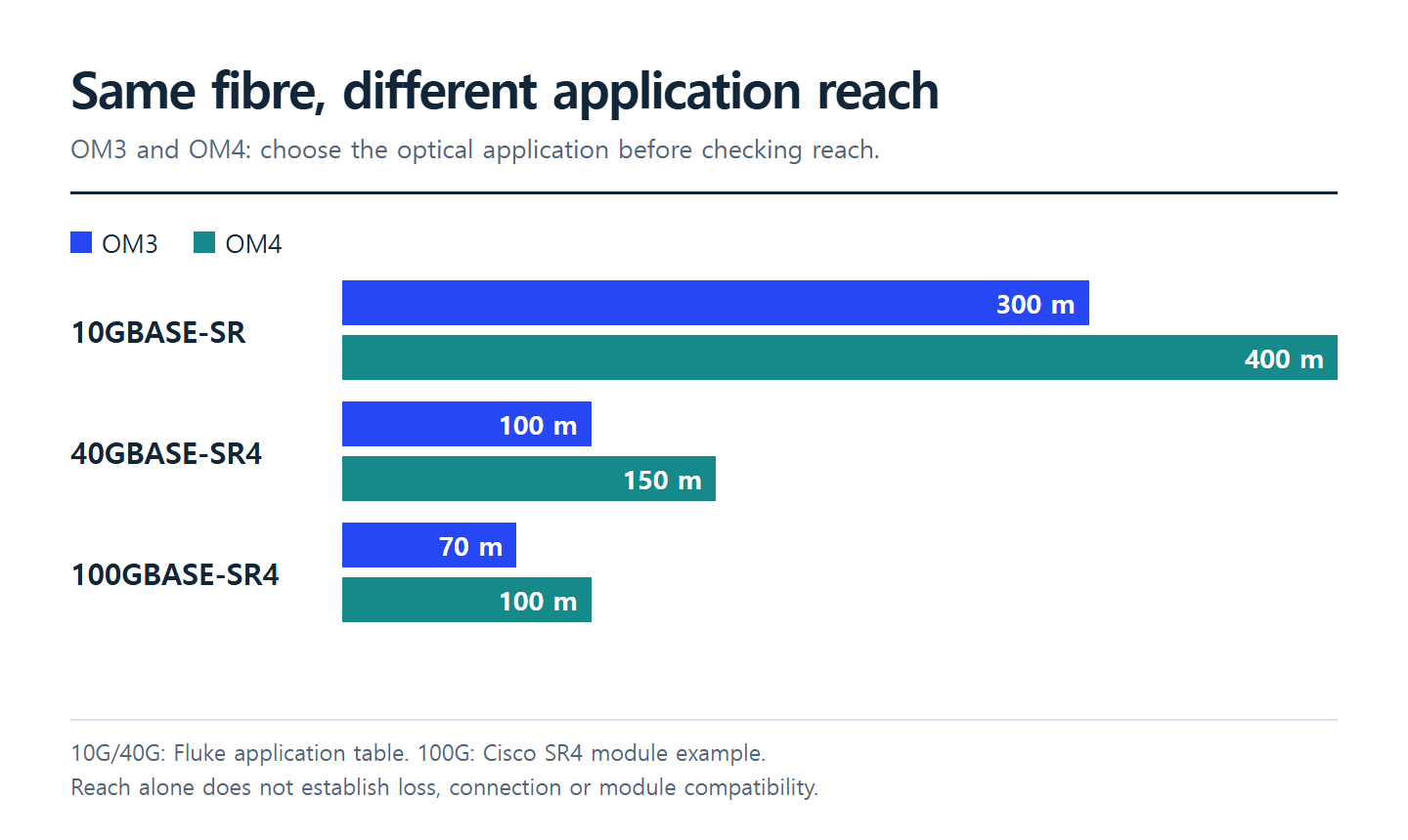
| 10GBASE-SR | 33 m | 82 m | 300 m | 400 m | 400 m |
| 40GBASE-SR4 | Outside this table's supported options | Outside this table's supported options | 100 m | 150 m | 150 m |
| 100GBASE-SR4, Cisco example | Outside this table's supported options | Outside this table's supported options | 70 m | 100 m | Check the specific module |
The first two rows follow Fluke's application table. The third uses the Cisco QSFP-100G-SR4-S example. Older 160 MHz·km, 62.5 µm fibre can reduce 10GBASE-SR reach to 26 m, so a legacy reel cannot be qualified from a casual OM1 label alone. Vendor-specific extensions apply only to the products and conditions that support them.
 Application-specific OM3 and OM4 reachView original
The supplied chart's 550 m for OM4 at 10G and combined 150 m for 40G/100G are not universal limits. This lesson uses 400 m for 10GBASE-SR and 100 m for the named 100GBASE-SR4 OM4 example. SR10, SR4, BiDi and SWDM use different optical arrangements and must not be combined into one “100G” row. A particular Cisco 100G SR-BiDi product supports 150 m on OM5; that does not extend every 100G module to 150 m.
Single-mode also has no fixed mapping such as “10G equals 40 km” or “100G equals 100 km”. Optics class, wavelengths, transmit and receive limits, amplification, dispersion and nonlinear behaviour determine the system. An OS2 jacket marking cannot guarantee long-haul service.
6. Wavelength, connectors and colour
Wavelength belongs to the optical application, not to a single universal cable setting. The SR/SR4 examples here use 850 nm multimode transmission. Single-mode systems use several operating wavelengths, including 1310 and 1550 nm; PON has a specific upstream/downstream wavelength plan. Knowing two common wavelengths is not an interoperability test.
LC and SC describe connector formats. MPO describes a multifibre interface. A connector that fits does not establish matching fibre type, speed or wavelength. MPO designs require fibre count, active lanes, polarity and pin configuration to be checked. UPC and APC describe different endface polish arrangements and must not be directly mated in a conventional physical-contact connection.
Orange for OM1/OM2, aqua for OM3/OM4, lime green for OM5 and yellow for single-mode are common identification conventions, with product and regional exceptions. Use jacket markings, certificates and part numbers. Do not infer a fibre category from colour or a chart's launch year.
7. Reach and loss are separate constraints
A channel can fit the distance limit and still exceed its loss allowance because it contains too many connections. A low-loss multimode channel can still lack the bandwidth for a faster application. For single-mode, adequate received power does not by itself settle dispersion, reflection or receiver-overload concerns.
A basic planning expression is:
Channel loss = route length × attenuation at the operating wavelength + mated-connection losses + splice losses + other passive-component losses.
Add the required engineering margin and compare with the selected application's channel-loss limit. Where a specific limit applies, do not replace it with a simplistic transmit-minimum minus receiver-sensitivity calculation. Check maximum receive input, reach and bandwidth separately. Count mated connections, not individual connector plugs.
 A link selection sequence separating optics, cable and connectionsView original
Worked exercise: an 80 m OM4 channel
Assume attenuation of 3.0 dB/km at 850 nm, four mated connections at 0.30 dB each, two splices at 0.10 dB each and a 0.50 dB margin. These are teaching assumptions, not measured values or contractual acceptance limits.
- Fibre: 0.080 km × 3.0 dB/km = 0.24 dB.
- Connections: 4 × 0.30 dB = 1.20 dB.
- Splices: 2 × 0.10 dB = 0.20 dB.
- Estimated passive loss: 1.64 dB.
- Design value including margin: 2.14 dB.
If the exercise assigns the selected module a 1.90 dB channel-loss limit, the 2.14 dB design cannot be approved even though 80 m is within the OM4 SR4 example's reach. Reduce connections or select a connection arrangement with lower guaranteed loss, recalculate and measure the final channel. A favourable spreadsheet does not replace inspection, cleaning or loss testing.
8. What the purchase request must contain
Scroll horizontally to view a wide table.
| Item | Information to record |
|---|---|
| Endpoints | Device models, ports, supported optics and software constraints |
| Route | Installed length including patch cords and slack; indoor/outdoor conditions |
| Optical interface | Exact application, such as 100GBASE-SR4, and module part numbers |
| Fibre | Cabling category, required ITU subcategory and wavelength-dependent performance |
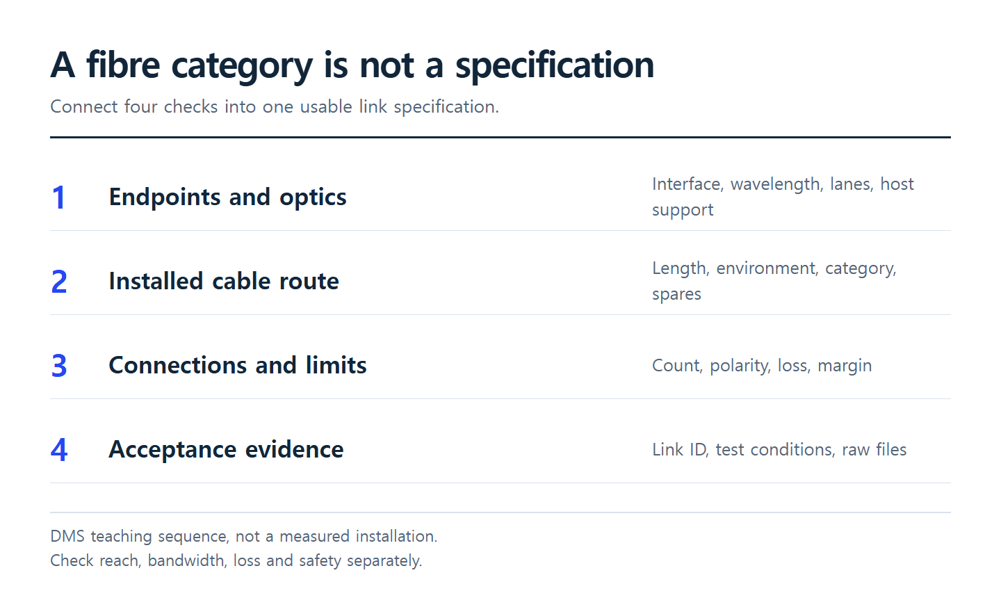
| Connections | Connector format, polish, mated count, MPO polarity/pins and splice count |
| Construction | Fibre and spare counts; tensile, crush, bend, water, temperature and fire requirements |
| Optical constraints | Channel loss, reflection, engineering margin and receive overload |
| Acceptance | Link ID, inspection, insertion loss, required OTDR settings, raw files and responsibility |
When using different module vendors, verify optical interface, wavelength, FEC, host support and interoperability rather than relying on matching advertised speed. A new installation also needs an upgrade review: future optics can require a different fibre count or connection architecture.
9. Review questions with answers
Can a 120 m OM4 channel use the 100GBASE-SR4 example in this lesson? No. It exceeds the named 100 m example. Consider another supported interface and reassess loss, fibre count and host support.
Does OM5 extend the reach of every 100G module? No. The optics must use the additional wavelength capability. A single-wavelength 850 nm application may gain nothing over OM4.
Can a G.657 cable be wound as tightly as convenient? No. Fibre bending-loss performance and the completed cable's mechanical bend limits are different requirements.
Can a compliant distance and estimated loss replace acceptance tests? No. Calculations predict a design; acceptance requires agreed tests and traceable measurements.
Continue to Part 2
How 5G and FTTH Shape Fiber Demand connects these link decisions to infrastructure demand and procurement exercises.
Sources and limits
- Fluke Networks, OM1 through OM5 and OS1/OS2: core size, bandwidth, 10GBASE-SR and 40GBASE-SR4 reach and loss requirements.
- Cisco, 100GBASE QSFP-100G Modules Data Sheet: product-specific SR4 and SR-BiDi reach and connectors. Direct page access was restricted; the public search-indexed datasheet tables were inspected. Recheck the current original before procurement.
- ITU-T G.652, G.655 and G.657: distinct single-mode fibre and cable characteristics.
- Corning, OM5 Multimode Fiber: background on OM5 and multiwavelength optics. Historical statements about standards adoption are not treated as current rules.
DMS prepared this lesson from public material checked on 13 October 2026. It does not reproduce the supplied chart's artwork or photographs. Chart launch dates, colours and reach claims are not used as procurement specifications. Distances describe named applications, not a guarantee that an installed channel will pass.